I’m going to preface this article by saying that I am not an expert at this! Many an expensive cutting tool has met its end while I “used” it to machine aluminum. There is a ton of good information from the world of machinists on the internet about cutting aluminum. Almost all of it is done with real metal mills and machining centers. Even a pretty dinky metal mill is much stiffer and less prone to vibration than a heavy duty router. This is a discussion around how to get decent results and not mess stuff up while using a tool that is ok but not ideal for a job.
The five big challenges I have had with cutting aluminum on various routers I have had are:
- alloy selection
- machine stiffness
- toolpath / strategy selection
- feeds and speeds
- chip clearing/cooling
- fixturing
Getting each of these sorted will make a huge difference in your success!
Safety!
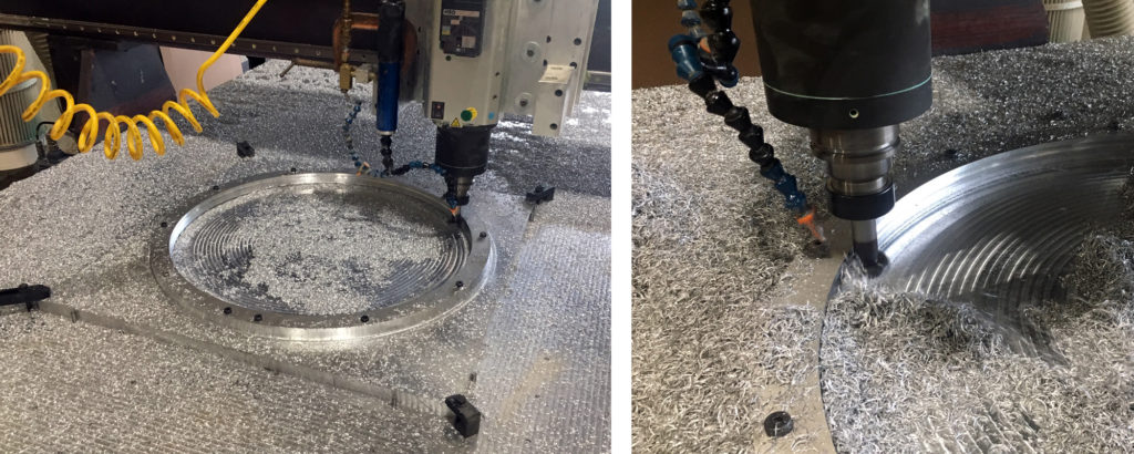
First off a bit about safety – because cutting metal brings some real concerns that you don’t have while cutting wood or plastic! There’s a reason commercial metal machining centers have enclosures. Flying chips and coolant make a huge mess and also pose real danger to operators. The internet is full of videos of machines flicking parts out of vises and cutters braking off and going flying. With metal machining, the chunks are heavier, sharper and hotter. Wear safety glasses at all times while machining aluminum!
Holding your material securely is very important. Because of the strength of the aluminum and the increased cutting forces, small parts and offcuts can get chucked with great force and speed – which is super scary. It isn’t unreasonable to rig up a shield or a curtain to protect yourself!
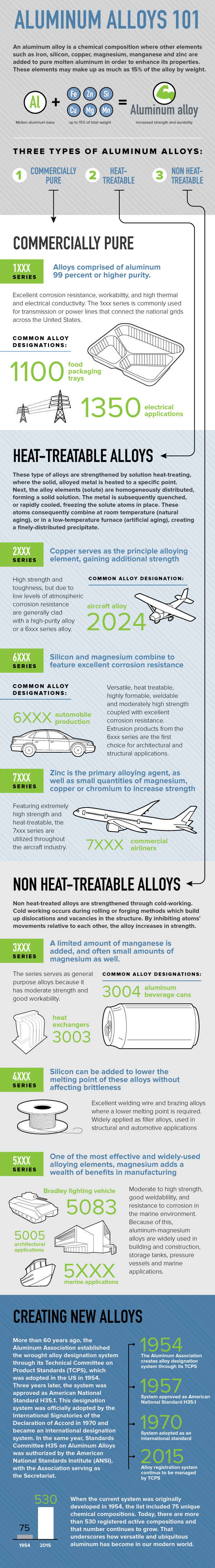
Alloy Selection: What type of aluminum?
Aluminum is most often alloyed with other metals to enhance specific properties. An overview can be found here: Aluminum Alloys 101. Generally, the best machining alloys are the 6xxx series. This is good because they are very common and easy to get. Most extrusion is 6xxx alloy. The “xxx” means that there are lots of sub types of 6-series aluminum. 6061 is very common and is a good option for machining. I have machined 5xxx series sheet – once when a customer brought it to me – and it was a disaster on a router. Very gummy and prone to loading up cutters. Lesson learned. If at all possible, stick to 6xxx series alloys.
Heat treating (for those alloys where it works) also effects the hardness of the material. Heat treat is shown as a number following the letter “T” – like “6061-T6.” Generally heat treated alloys will be better (harder and less gummy) for machining. The non-heat treated material will be designated “T3” or “T4” and the heat treated (or aged) will be “T5” or “T6” – so all else being equal, if you want to machine it, make sure you get heat treated material. Heat treated material is also a bit stronger. Anyone who sells metal will be much more aware of the details than I am – so ask before you buy.
If I had to choose something to machine, it would be “6061-T6” for general purpose stuff or “Mic-6” cast plate for things that have to be stable or benefit from flat initial stock. Mic-6 is an Alcoa product designation but the name is often used kind of like “Kleenex” or “Xerox” to mean just “cast plate”. It is cast in a sheet instead of extruded so it has minimal internal stress and won’t warp when machined. It also comes ground super flat – but it’s more expensive!
Cutting Loads
You can test how (un)stiff your machine is by getting a dial indicator and placing it to read deflection in some axis somewhere near the head. Grab the machine (spindle off) and pull on it as hard as you dare. Unless you have a really rugged machine it will move a lot. I had machine that cut wood very nicely and accurately but would deflect .06” (1.5mm) with just the pressure I could make with my hands. The truth is – if you’re doing it right – a cutter doing a normal machining operation creates a lot less load on the machine than you’d think! Match this with the software in machine controls that is designed to control accelerations gracefully – and a pretty floppy machine can make very accurate cuts.
When you make the jump from cutting wood (density up to 50lbs/cubic ft.) to aluminum (about 170lbs/cubic ft) you are cutting something four times as dense. As you’d expect the cutting loads go way up if you take the same cutter at the same speed – so don’t do that!
For more about machining aluminum with light-duty machines, check out this excellent video from NYCCNC: Shapeoko Feeds & Speeds and Machining Tips!
Cutting Strategies
With a floppy machine you have to keep loads on the tool low and uniform or it will leave an ugly surface. Modern CAM packages have elegant toolpath strategies for maintaining consistent cutter load. For roughing, these strategies (called “Adaptive” for Autodesk products, “Dynamic” for Mastercam, etc.) are very effective and will give much better results. This is especially noticeable in corners or pockets where traditional strategies force the cutter to take a huge mouthful right as it changes directions!
The axial depth of cut (how deep your cutter flutes are engaged) is important too. If you have a low-power spindle with plenty of RPM, you may find it is better to move faster but take a shallow depth cut with an “Adaptive” style cutting strategy. Chip clearing will be easier and you may get better process reliability at the cost of only a little speed.
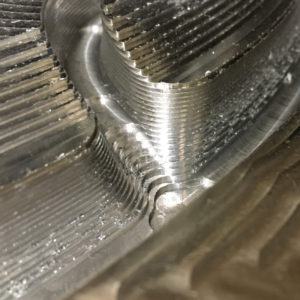
For finishing operations, especially 3D ones with a ball-end mill – a “pre-finishing” approach will really help make the final surface nice. To do this you just make a set of operations that are the same as your finishing paths, but that leave a small bit of material (.02″ / 0.5mm) and use a larger step-over by 2 to 4X. These paths will leave a very uniform layer of material for the final finishing operations to remove. In corners, this will reduce the volume of material that needs to be removed and will eliminate steps from a roughing pass that can put uneven load on your cutter. Trying to muscle through a stepped rough finish with a finishing cutter can cause the bit (or machine) to deflect telegraphing the roughing steps into the finished part.
For more about basic approaches to 3D machining, check out my article: INTRODUCTION TO CNC MACHINING SURFACES
Feeds and Speeds
There are formulas to calculate the right range of cutting parameters for a given tool in a given material and machinists put a lot of effort into calculating “feeds and speeds.” Most tool suppliers will have specific guidelines which are very helpful. Here are some good resources to help with this:
- Harvey Tool Blog: Speeds and Feeds 101
- NYC CNC: Speeds & Feeds Tutorial for CNC Machines! WW164
Here’s a quick overview of what you need to know to choose a reasonable feed rate and RPM for your situation (Sorry, no metric yet!) :
Surface Feet per Minute (SFM): This is how far a point on the surface – say the tip of a flute of the tool travels in one minute. Imagine you roll the tool along a surface next to a ruler. SFM is how far the tool would roll in a minute. This is not something we calculate – it’s more of a metric to say “how fast” we are cutting. Good guidelines can be taken from a table provided by a tooling manufacturer – or from rough guidelines for a material. For carbide tooling in aluminum this is about 600-1500 – higher for finishing, lower for roughing. For stainless steels and other heavy duty stuff, ideal SFM can be below 100.
Revolutions per Minute (RPM): This is just how fast the tool is spinning. The second hand on a clock goes 1 RPM. Hopefully your tool will be faster. Routers typically have plenty of RPM range, but not much low-end torque, so you’ll probably do best in the 8,000-25,000 RPM range.
Cutter Diameter (D): This is the diameter of the cutting part of the cutter.
Cutter Number of Teeth (T): How many flutes/teeth does the cutting tool have? For aluminum, the fewer the better. Two is almost always plenty, and for sheet cutting or roughing without flood coolant, single flute cutters are awesome! (see below for more)
To make some useful calculations, we’ll start with a standard of 1000 SFM for our aluminum and D – the diameter of our tool. Lets imagine we have a nice 1/4” two-flute carbide up-spiral cutter. So D is going to be .25” and T will be 2.
Using this formula, we can calculate the RPM we will use:
RPM = (3.8 x SFM) / D
15200 = (3.8 x 1000) / .25
So we have our theoretical RPM! Now we can calculate how fast to run the machine, using two additional variables:
Chip-load Per Tooth (CPT): This is how much of a bite each tooth takes at the full programmed feed rate. Generally expressed in thousandths of an inch, for example our 1/4” carbide cutter might work well with 0.002” CPT.
Inches per Minute (IPM): This is the cutting speed – how fast the spindle moves through the material.
So, we can calculate the feed rate (IPM) from RPM, chip load per tooth (CPT), and the number of teeth (T) on the tool:
IPM = RPM x CPT x T
With our 15,200 RPM speed and 0.002” CPT on a two flute tool:
60.8 =15200 x 0.002 x 2
Our feed rate will be 60.8 inches per minute!
This is a good start – and will probably work ok. Checking with manufacturer’s published data on SFM and Chip-load will allow you to use more tool-specific numbers and get better results. The 0.002” chip load we use in this example is on the low side for roughing with a 1/4” tool, and you may be able to crank it up quite a bit in the feed rate department without problems.
Don’t try to make things go better by going really slow! This is almost as bad as going too fast because instead of breaking your cutter right away – it will rub and generate heat and gum up – and then break. Resist the temptation to slow it down too much. You want to make sure the chips coming off the cut are actual chips. Grab a caliper and measure one – ideally the thickness at the “fat end” should be close the chip load per tooth value you chose.
Also you should be “climb cutting” by default – an option in your CAM software. This will take the fat part of the chip first and avoid rubbing and generating heat. Check out this quick article by Harvey Tool about the difference between climb and conventional milling.
Cutters
Cutter choice makes a big difference, especially if you are limited in your use of coolant. Many standard cutters are optimized for use with coolant in an enclosed machining center. If you’re using no coolant or just air-blast, you’ll need to be careful not to load up your cutters with rubbed or gummy metal. Avoid anything with more than two flutes. If you’re finishing a three-flute ball-end can be ok, but it is more prone to loading. The additional flutes increase the stiffness of the cutter though which can be helpful.
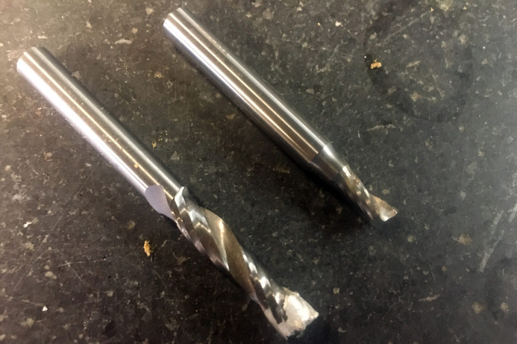
Single flute tools are a huge help when cutting aluminum on a router. Typically you have plenty of spindle RPM but not much stiffness, and chip clearing is an issue. Single flute cutters are a “best fit” for this scenario. Look at this – the two flute gummed up and the single flute worked like a champ!
You’ll also want to limit the “stick-out” of your tools to the minimum. Figure out how deep you need to cut and then add a little margin – maybe 0.125″ / 3mm – just so you don’t crash it. Short “stub-length” tools are great!
Clearing Chips and Cooling
Once you are operating with reasonable “feeds and speeds” you are going to come to the next problem – how do you get chips out of the cut, and how do you keep the cutter cool? In an ideal world, the chips would be neatly sliced off and thrown well clear of the cut, taking all the heat that the cutting process generated away with them. This isn’t likely to happen… but you have options!

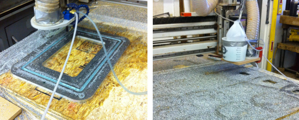
Your least messy option is compressed air – blowing chips out of the cut and keeping tool clear. Air itself doesn’t absorb much heat so this will only work for light cutting with no deep pockets… ideally with a single flute cutter or with a machining strategy that doesn’t involve single pass slotting. There are “cold air guns,” made by Vortec and others that work well, but any throttleable focused air blast should work ok.
Stepping up from air alone, you can use a coolant mist, or “minimum quantity lubrication” system. Fogbuster, Koolmist, and many others are common add-ons to CNC routers. You just need a reservoir and a nozzle and a compressed air line to the spindle area. There is enough coolant to provide some lubricity and to evaporate pulling away heat. It is combined with air to clear chips. It’s messy, but you can usually rig up some type of drainage system to keep liquid off the important motion and electrical bits. Minimum quantity lubricant systems are lighter on the air and more about providing a lubricant to the cut and less about clearing chips. Depending on the application, this may be plenty.
If you have a heavy duty machine and it is set up to handle it, flood coolant is excellent. It is the standard for milling metals in general and some routers can handle the flow of excess coolant off the table and back to the coolant pump. For light to medium aluminum work, you probably don’t need it. On a router it is unlikely to be the make or break issue because machines aren’t typically powerful or stiff enough to take heavy cuts.
Fixturing
How are you going to hold it down? Depending on your machine and your choice of coolant and chip clearing options, you have a bunch of ways you could do it…
Above you can see the simplest option – drill some holes where you won’t be machining and screw it down to a sheet of plywood! Here I have also put some plastic sheeting down to protect the MDF bed of the machine. This is not a production-ready option, but if you have to get it done before lunch-time then this is worth a shot. You may have to use tabs (probably an option in your CAM software) to hold small pieces in place.
If your machine has a vacuum table, that is a good option if you have enough vacuum capacity to hold the sheet down as you cut more and more holes through it. Vacuum is great for production cutting, where you can set up a gasketed fixture that only holds the part where it will not be cut through. Given that aluminum is expensive and it is very hard to re-index a sheet that has shifted, it may be good to use a “belt and suspenders” approach and also mechanically fasten or index large (especially thin) sheets against fixed stops in addition to using vacuum.
The way I prefer (if possible) is to actually clamp the material down with some kind of strap clamp arraignment. This works better for thicker material. Below is a picture of me cutting some 3/8” plate on a machine with a thick aluminum plate for a table. This table has tapped holes every few inches so strap clamps can be used. Best. Table. Ever! You can see some standard metal clamps like you’d see in a machine shop as well as a home-made MDF one which has longer reach and dampens vibration. I’m using a 1/4” single flute end mill with cold air blast.
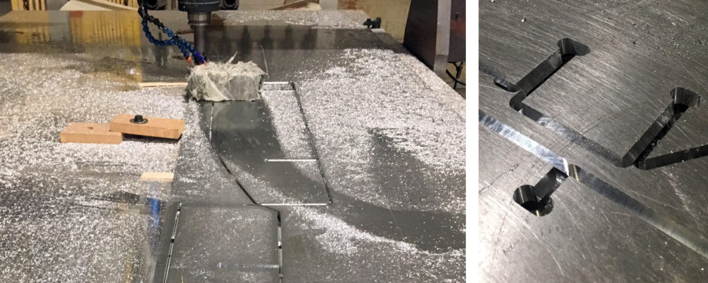
There are a few other strange things visible in the picture above – first, the paint stir sticks slid under the plate every foot or so. These let me cut through the work-piece without cutting into the aluminum machine table. They also help drop chips out of the slots as they are cut through. The other strange thing is the lead brick covered in plastic tape. The plastic tape is so you don’t touch the lead, and the lead is there to dampen vibrations in the plate. The operator has to move it around and keep it clear of the cutting head, but it keeps the sheet from chattering especially as large parts are cut almost free – except where they are held with tabs. Not pretty, but worked out well though!
You can also use vises like on a machining center. I have (very rarely) bolted a pair of vises to the table in a row and used them to hold extrusion for machining. Other people do this all the time and it worked great for me too – but my experience is limited! The machinists of the internet have got this covered.
Conclusions
Now you know what I know. It’s not comprehensive but its a start, and I hope it saves you a broken cutter or some other headache!
Links:
- NYC CNC: Shapeoko Feeds & Speeds and Machining Tips!
- Harvey Tool: Attacking Aluminum: A Machining Guide
- Harvey Tool Blog: Speeds and Feeds 101
- NYC CNC: Speeds & Feeds Tutorial for CNC Machines! WW164
Note:
This article contains information that reflects my opinions – I make no promises about its usefulness! It may contain mistakes (please let me know if you find some!) and will include prejudices based on my limited experience. If you disagree with anything here, please get in touch. This is not just for me to share what I know, but to learn from others. I will gladly insert additional information and differing opinions so readers are more aware of the diversity of “right” answers!
Change Log:
Updated: 12/5/19 – Heat treat and Mic 6, climb cutting, slow warning and fix mistakes in calculation.
Updated: 1/9/21 – Added cutters, strategies sections, links.