Project by North Shore Composites (2016)
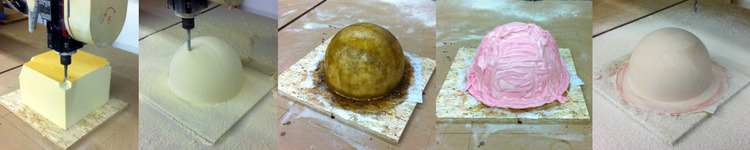
First, an overview of the process: a hard shell over a soft middle part…
“I think you’re going to be ok here… they have a thin candy shell. Surprised you didn’t know that.”
This example is going to show how large (or not so large) patterns and plugs can be made using light-weight foam as a base with a thin skin of fiberglass and tooling paste to form a hard machined surface. Kind of like the M&M’s in the dashboard, the hard shell is only fancy where in needs to be – unlike tooling board which costs the big bucks even where it’s just filler. For large scale plugs and direct molds, this is just the ticket and the only viable alternative to “stick building” from wood and sheet goods… until large scale 3D printing gets more accessible.
More about paste tools here: Building Big with Tooling Paste
The Part
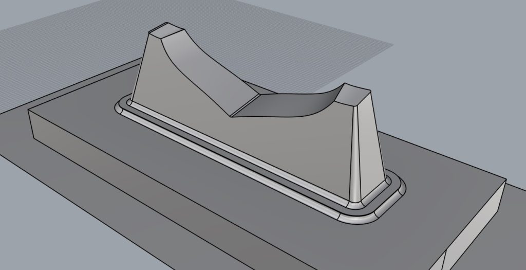
The part here is going to be a “bunk” for storing racing dinghys on floats for college sailing teams. The one shown is for FJ’s, a common collegiate racing class. We designed this from a 3D scan so the boats could be stored either upright for day-to-day use or upside down for winter storage. It’s a simple shape:
We needed to build tooling that would be used to build dozens – maybe hundreds – of these parts. Our two potential building methods were:
- Hand-laid e-glass/polyester with Coremat
- Infused e-glass/polyester with Rovicore and a re-usable silicone bag
If we were just going to hand lay these we wouldn’t need such a big flange, but for re-usable bags, a minimum of 8″ is good (more is better) to accommodate the perimeter vacuum manifold and the seal features. The finish was to be glossy gelcoat with some hardware and decals applied. The other main thing we thought about at this stage was the trimming process. These needed to be bolted to a dock at the corners and would ideally have no sharp corners to catch lines or feet.
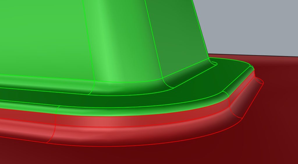
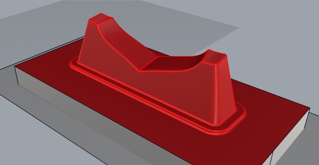
We wanted the part to have a radius turned down into the dock: to look good, be safe and protect and exposed fibers from damage. The trimming was designed to be done with a router (we used a CNC because it was faster and safer) and a diamond flywheel. The image to the left shows the part (green) and the discarded and flange area (red) – the trim line is planar which makes this very easy!
Building the Plugs
We decided to use paste for these because we had some on hand and it looked to be cheaper than using tooling board. The project included a second plug and tooling for a similar dinghy, so this is only half the job. We were concerned about lift-lines printing into the finished mold too, but this would probably not have been a problem with 30-40lb tooling board. These are about 5’/1.5m across so it would have been similar price to use tooling board, and much fewer steps – and probably could have been done with a hollow core because the molds were hand laid and not subject to the rigors of vacuum bagging.
This is about the size where tooling board starts to become a less-obvious choice. As you get bigger the cost savings of using a cheap substrate – in this case 2lb Trymer Urethane foam – become much more compelling! Smaller, and tooling board or MDF are obvious choices.
Foam Substrate and Base
The first step was to offset the model for the thickness of the glass and paste to be applied. We used several layers of 1oz (300g) chopped strand mat set in general purpose polyester resin and planned to leave 1/4″-3/8″ of paste on the plug. The deduction we used was about 1/2″(12mm). In the 3D model, we deducted – and our nice radii went away! We’ll get those back with 80 grit.
At the same time, we glued up blocks of the urethane foam with Gorilla Glue. These were made roughly larger then the finished surface. Because it is 2lb foam, the roughing operation can involve some deep cuts! The foam blocks were glued to stable plywood (actually Advantech chip-board which is awesome for this) bucks made from 6″ thick “egg-crate” style assemblies. The shrinkage of the fiberglass laminate and the paste can bend weakly-supported plugs and it is handy to have good clamping spots for fixturing things on the machine. These went on the router (a 5’x10′ Motionmaster 5-axis with 36″ of z-stroke) and were machined to the deducted shape.
Laminate
From here we applied about 1/8″ of chopped strand mat with general purpose (laminating) polyester resin. The resin is compatible with the urethane foam. If you need to use EPS foam (eaten by styrene) you can use a product like (ATC Poly-protect) which isolates the EPS foam from the styrene in the resin.
Paste
After the laminate cured, we sprayed on three applications of ATC T-27 tooling paste from a Magnum Venus Putty 2000 machine. This was our second go with the spray method, and it wasn’t a complete success! There were definitely pinholes and some areas where it sagged and we had to re-apply paste by hand.
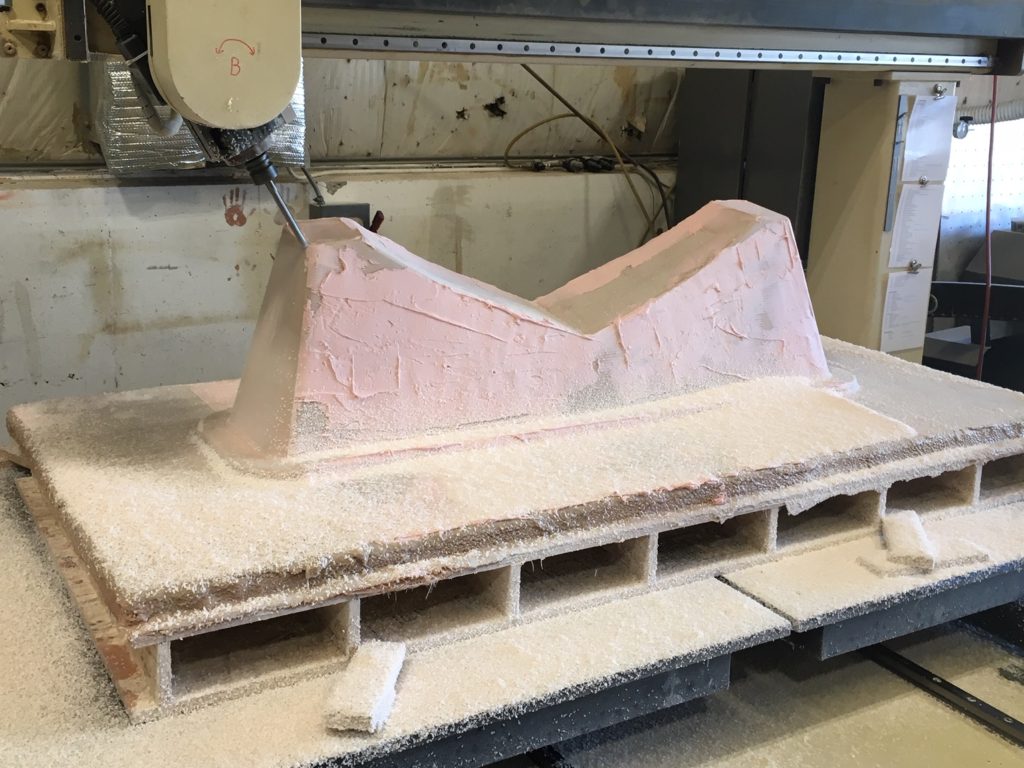
Rough-machining the urethane foam from a block. 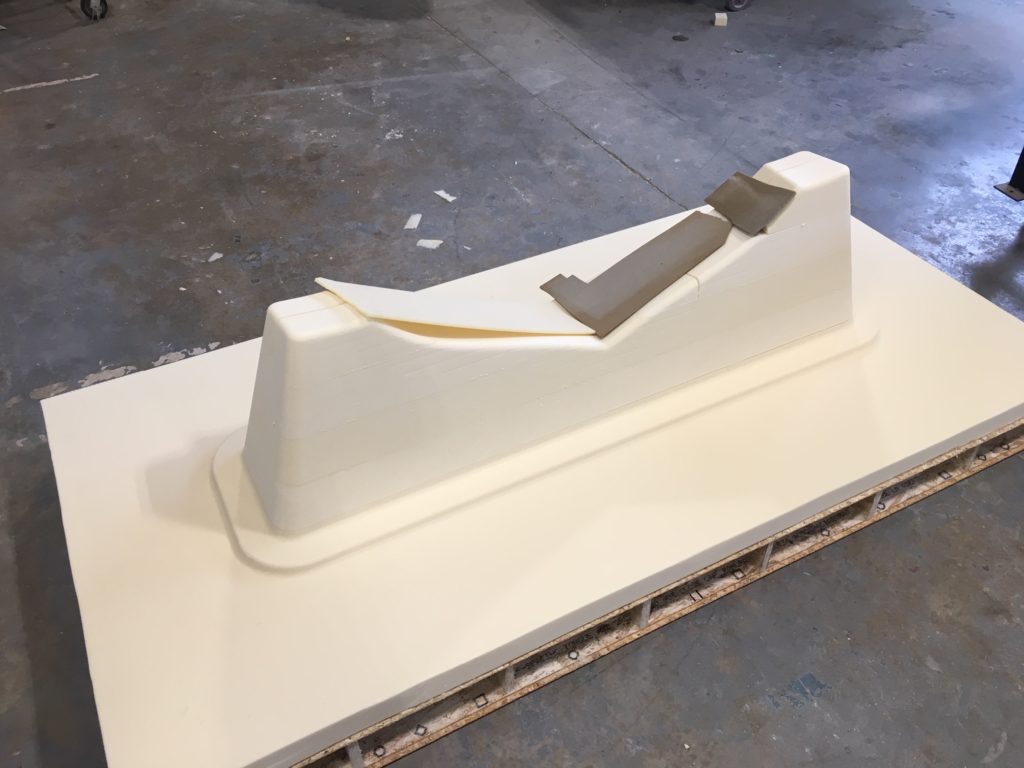
Machined foam ready for a test-fit. 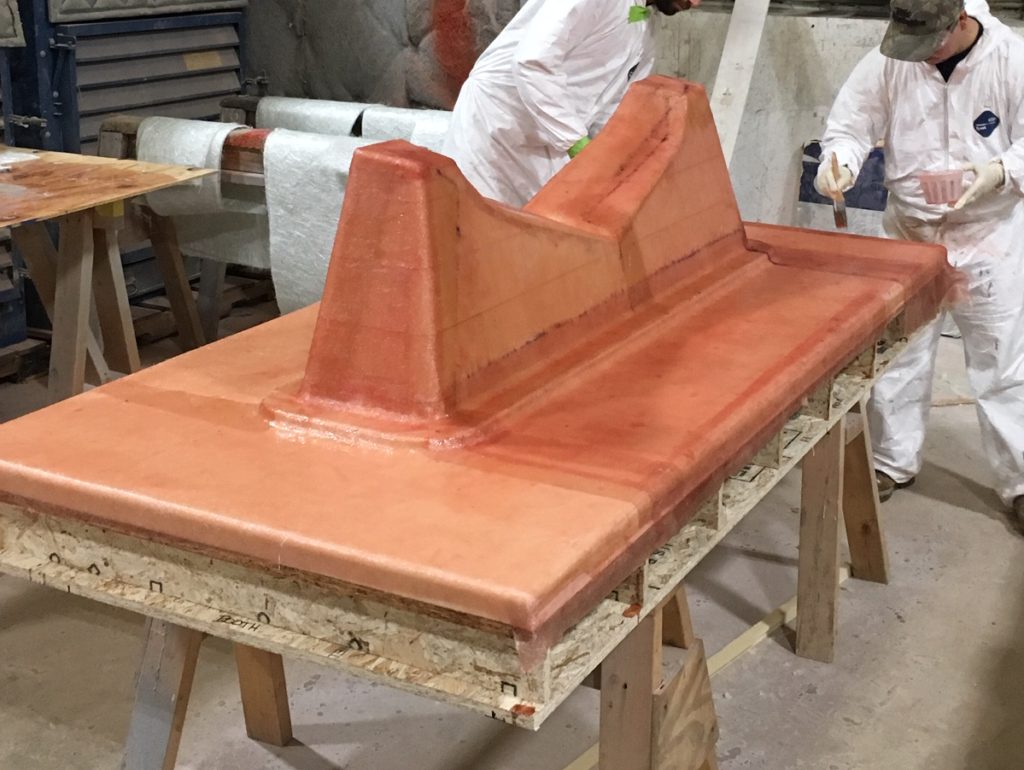
Laminating the foam with several layers of chopped strand mat and polyester resin. 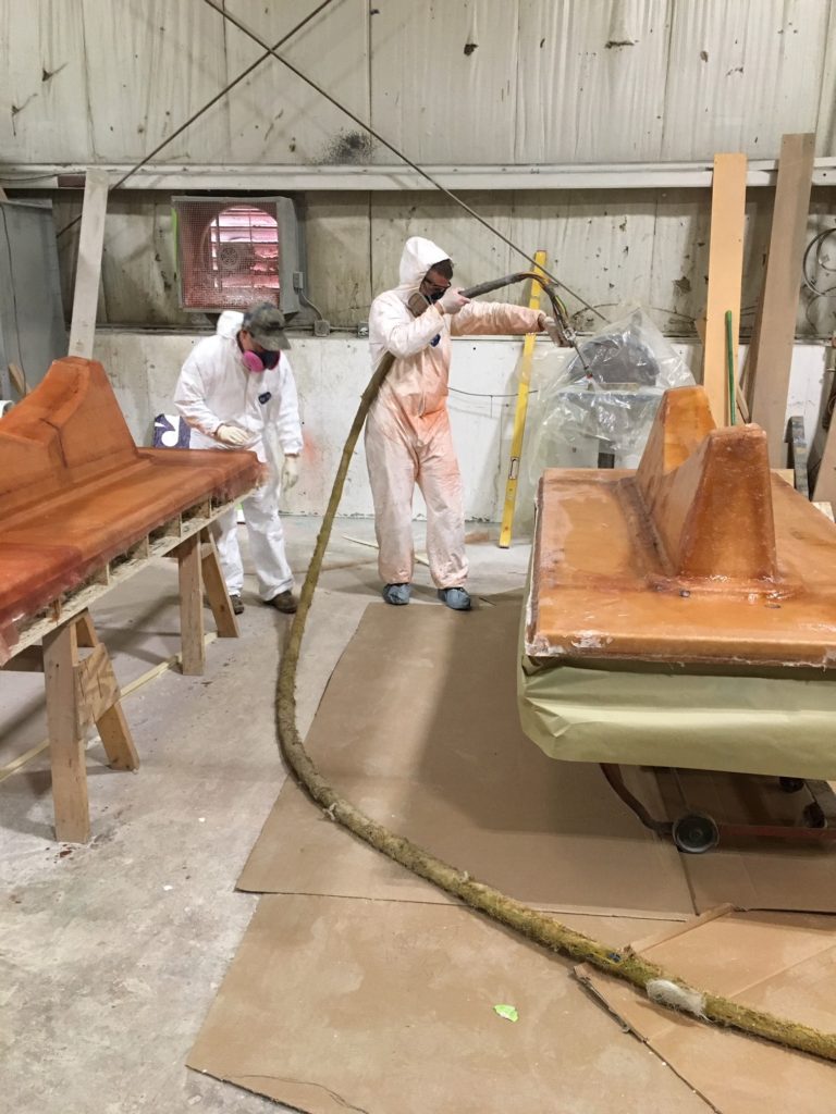
Spraying paste. 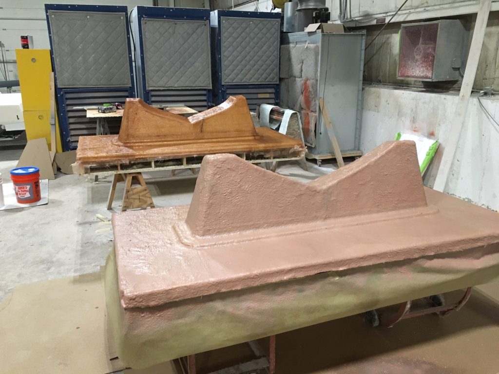
First round of paste. 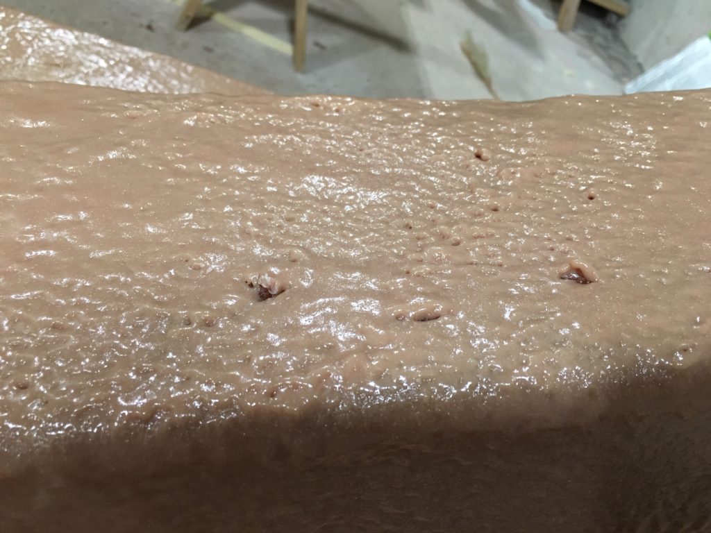
Paste surface – we needed more practice with this and had to come back and re-fill areas.
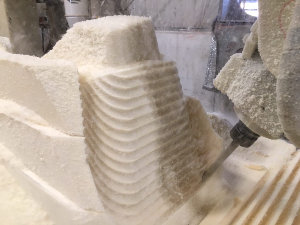
Final Machining
Overall it went ok and the buck went back on the CNC for final machining. To re-position the part, now covered with a variable thickness layer of paste and fiberglass, we had made marks and clamping holes in the wood base and these could be re-aligned within less than 1mm of where they had been for milling the foam. Its good to have a plan for this so you leave an even layer of paste on the surface during final machining.
Machining the paste – here you can see the fills made with some different type of paste – ATC T28, which is made for extruding. 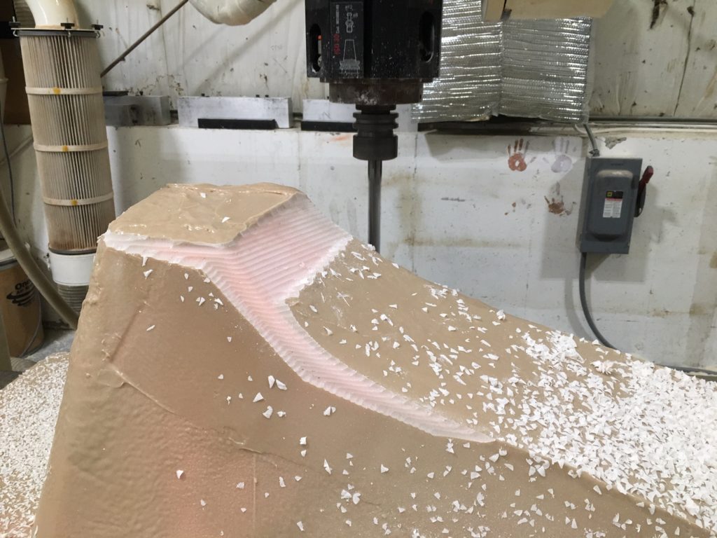
Starting to mill away the excess paste. 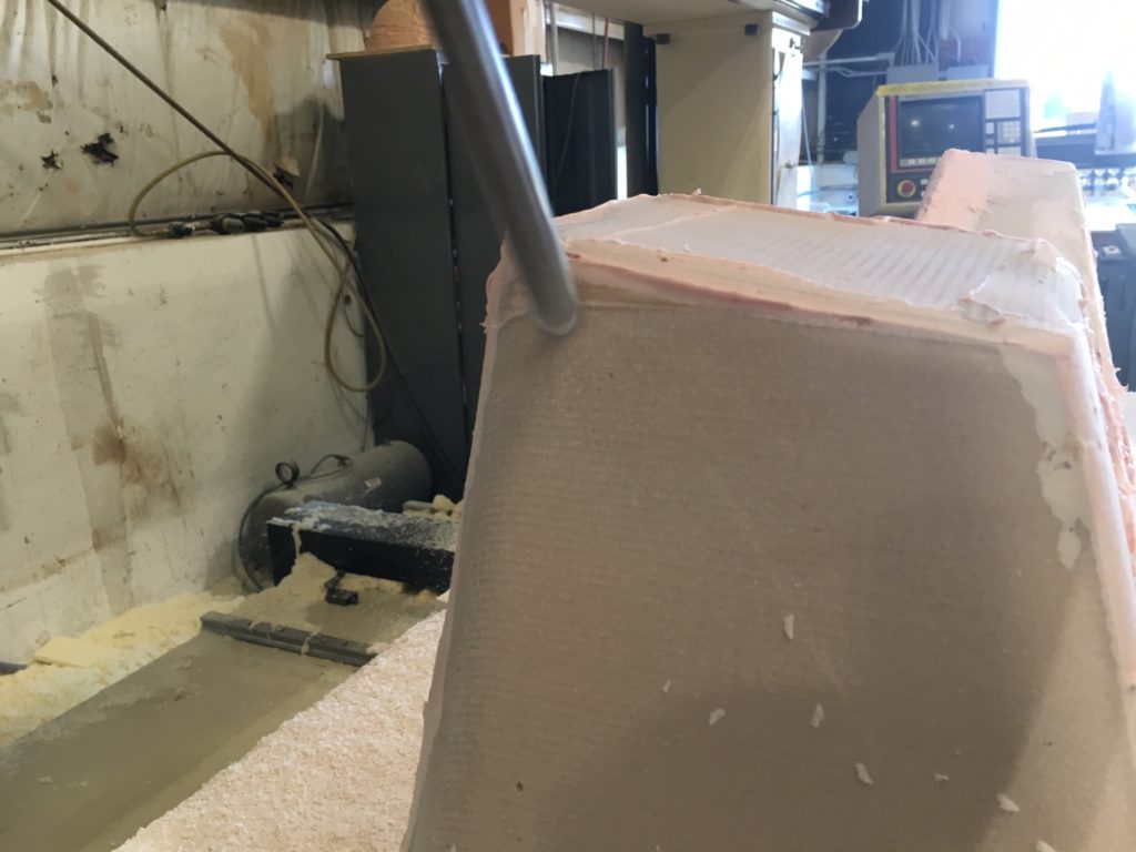
Had to re-fill some corners before the final pass.
The machining was done with ball-end carbide cutters. We had best results doing a pre-finishing pass leaving 0.125″/3mm (or a bit less) of putty and a wider step-over and then coming back and finish-machining with a finer step-over. This also allowed for filling any low spots where we had under-applied the putty – before the final surfacing operation. Our machine was not able to make a nice surface in one pass as it deflected when the paste was thick – through all those nice sags and drips! Beefier CNC machinery may be able to tear through paste right to the final surface, but my advice would be to pre-finish to give an even load on the cutting tool for the final finishing pass. You’d be amazed at how much paste finds its way into inside corners!
Safety Note: The shavings/dust from polyester tooling paste is super flammable and can spontaneously catch fire! We always cleaned up well and put it in metal drums outside (and fare away from) the building.
Finishing
The finishing was done with Duratec primers. We started with EZ-Sand (707-061) and finished with standard primer (707-002) – several rounds of sanding and spraying working up to 1200 grit before switching to buffing compound. This is a lot of work and needs to be done very carefully for good results. The paste provided a stable substrate and we didn’t have problems with filled areas printing through during buffing.
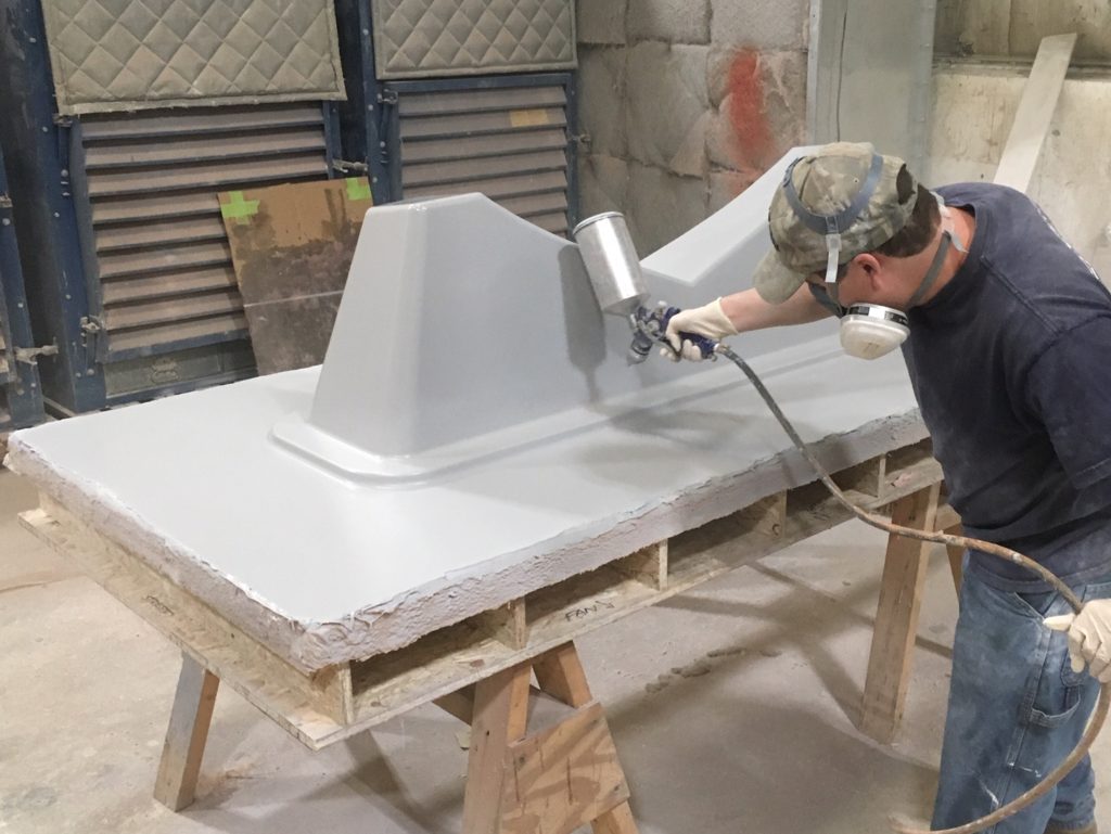
Spraying primer on the paste surface 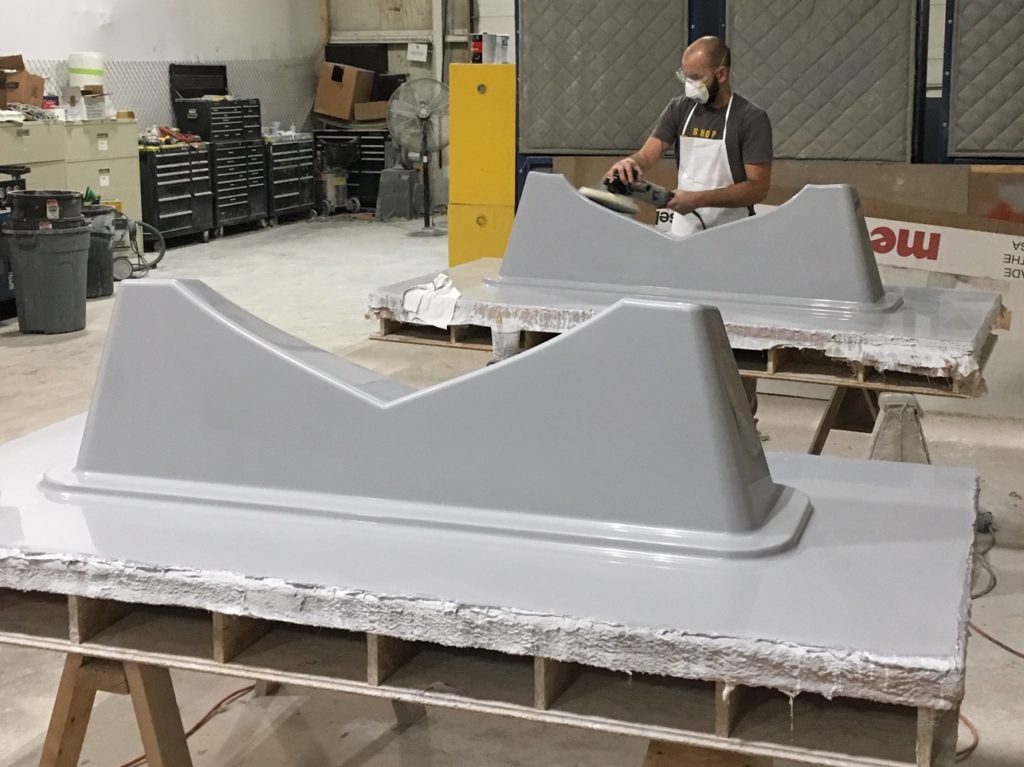
After lots of sanding… buffing the final surface.
When Paste?
In hindsight, it may have been easier to use a 30-40lb tooling board for this. Certainly would have shortened the time to completion with only one operation on the machine. But it would have been a lot of tooling board and the roughing time would have been substantial, even with a carefully fit glue-up. Some money could be saved by gluing up lighter (thus cheaper) tooling board in the middle and leaving the high density stuff for the surfaces, but this involves lots of planning and careful glue-up.
My conclusion is that this is the minimum sized part where paste makes sense. Unless you are a tooling factory and are constantly building bucks, laminating and spraying/extruding paste it is a lot of work to set up and put away the putty machine. Still, the plugs came out awesome and the production molds worked great!