Almost all composite processes require some kind of mold to give them their shape. The things that give composite parts their surface geometry are generally called “molds” – while “tooling” is a term that includes molds but also other parts of the assembly of stuff that gives a part it’s shape. You can use the terms interchangeably up to a point, but keep in mind that “tooling” is more generic.
“The Part”
We’re going to use this example part to look at the types of tooling – how the process works and what things are called. This part is pure fiction but it has features that are common in parts built with composite processes.

Typical Production Tooling: Plug / Pattern and then Mold
So you have a shape in mind that you would like to make in composite. In most cases you’ll build an object that is exactly the shape that you want to new part to be – well the shape of its outside shiny surface. You can make this out of whatever works best – wood, fiberglass, metal, plastic or in most cases a mix of several materials. You call this dummy part the “plug” or the “pattern.” It needs to be every bit as nice and shiny as you want the final part to come out – better even! It also needs to incorporate any flanges or locating features that you will need to make the final part.

The shape on the left is the plug – with all the flanges you’ll need for your vacuum bag or for some trimming room once you have the parts made. See how the part is “inside” the plug – the middle image shows the 3D model overlapped with the white part “hiding” inside the gray plug geometry. Once you have a plug, the next step is building a “mold” – this is the cavity (or convex shape) into which the part will be laminated. On the right, the mold has been laminated over the plug and a bit of “support structure” has been added to make it stable and easy to handle.
If all goes well the mold will pick up all the features and shinyness of the plug and then allow you to make new parts that share the plug’s exact original surface shape.

Here on the left, the mold has been removed from the plug. It is ready to make parts! In the middle, a part has been “laminated” in the mold (in reality the edges would be built longer and trimmed – but we’re in CAD perfection-land here) and then demolded on the far right. When you design molds, it is important to think about what side of your part will be the “tool side” or “mold face” of the part. This is the side that is built directly into the mold and will come out smooth and pretty – and often with gelcoat. The upper of the two part images shows the “mold face” and the lower the “back” or if you’re vacuum bagging, the “bag side” of the part. This is often a little sloppy and may need to be hidden or hand-finished. There are options to mold this surface as well. If that is important for your parts, look into “compression molding”, “RTM/VARTM” or “squish molding.”
Don’t forget that in all these steps it is necessary to use a release agent between the plug and the mold and then between the mold and the parts you are producing. There’s a lot to getting parts to “release” cleanly from a mold and release coatings are (will be) covered elsewhere on this site – and lots of other places – in more detail. It is always good to test new release systems in low-stakes situations. I have even made up a “dummy surface” with the same finish as the plug when using a new release system – many factors will come into play including the materials used to surface your plug. Manufacturers of release systems will provide documentation and advice on how not to screw things up – or at least where to start. Even so, almost all composites fabricators have horror stories of release-coat drama – resulting in wasted time and rework at best and total loss of mold and part in the worst case. Don’t assume it will work – test first!
One-offs and Shortcuts
There are shortcuts, which often make sense for building one-off of low-volume items. You can build a plug intentionally undersized – the shape of the “inside” of a part and then manually finish the outside of your part. This is often called “male-molding” and it leaves the mold-side of the part shiny. This often makes sense for large one-off things where a male mold is way cheaper to build than a female one – boats for example. I am a big proponent of male molds for boat hulls if you are only making one!
Male Molds
So… male molds vs. female molds – this gets kind of confusing when we bring the birds and bees bit into it… but it works for pipe fittings so we’ll go with it. Basically, a male mold is one where the part is built “over” a convex surface:

You would then manually finish (fair, prime and paint) the top side of the part if needed. The term “male molding” implies that you are both molding over a convex shape, and that there is some drawback to that and that you’d ideally do it the other way – by this is faster or cheaper. If this is how you would make the part even if you made a thousand of them – then just call it “molding”.
Female Molds
Female molds are ones where the part is build inside a concave surface. For most shapes like car parts, airplane wings, bicycles and boats, the outside is the surface that needs to be perfect and shiny. These are usually female molded. Here is our part in a female mold:

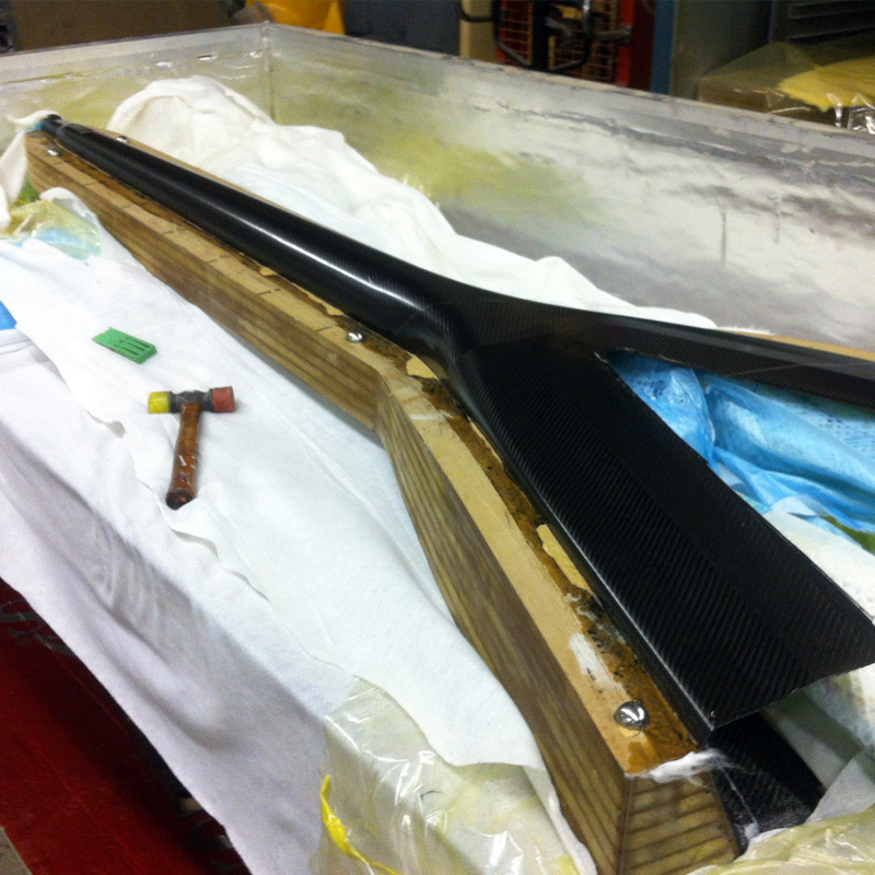
This looks just like our orange “production” mold from above, but this is made in one step by machining a block of something – MDF, tooling board, aluminum – something that can be made directly to the mold surface geometry of the part. The picture to the right shows a carbon one-off part in a female mold. This mold is split top-to-bottom and has metal balls to align it.
If you are making molds out of metal, they are usually machined directly into the “mold” stage, because you don’t need the plug step. Metal molds are great for small or high-volume parts. Check out how bicycle builders make their frames – some very clever metal molds going on in that industry!
The fact that a tool surface is “male” or “female” is unrelated to whether it is a plug or a mold – even though for some times it feels like this should be the case. For boats a “hull plug” looks a lot like a “male mold” – the male mold is just smaller to account for the thickness of the hull that will be built over it.
Winning Details
There are some basic considerations that you need to take into account when designing parts for molding. First off, the geometry of the part needs to let it come out of the mold. This is the same as in foundry work and injection molding – there needs to be some “draft” to the part. Draft is the slight angle in the sides of things that are roughly co-linear with the direction you have to pull the part to release if from the mold. Here’s a picture:

The red lines in the middle show that the sides of the part aren’t exactly up and down – they are angled at 5 degrees from vertical. This means that once the part is physically separated from the mold, it will immediately get looser and looser as it separates further. If there was no draft angle to the sides of the mold, you’d have to drag the part up the sides of the mold and any variation or error could result in the part binding up and getting stuck. There are cases where you can ignore draft angle – but mainly for one-off parts where the tools gets messed up in releasing the part. If you need parallel sides of a part, you should consider splitting your mold into two parts.
The other thing to be mindful of are the radii on the corners of the part. Composites don’t like sharp corners. It can be done, but usually by cheating and “filling” the sharp area with non-structural material. Generally you should shoot for as large a radius as possible. Avoid radii less than the laminate thickness because they will force a hard corner on the inside. Ideally go for two (or more) times the laminate thickness to account for slip joints.
Check out my article: SLIP JOINTS AND WHY YOU NEED THEM!
This part looks like it is meant to bond onto a surface with those big external flanges. See how the flange is a uniform width? This makes trimming easier and looks nice. Flanges are a great way to join composite parts together without secondary lamination. Think about how your parts will fit together and try to incorporate as much detail into the molds to make it easy to join parts during assembly. Tooling is probably the most important aspect of designing composites manufacturing processes. It can certainly make things easy or hard depending on how well thought out it is. If you get it right, the parts practically build themselves!
Conclusions
This is a quick overview of what to call different parts of tooling. These terms are used throughout the industry – and the material on EC! I hope this helps make things more obvious!