The goal was to have a 5kg shell. Initially it was going to be finished clear, so there couldn’t be any real fairing compound. Also, fairing adds weight. There weren’t any heat issues but it would have to exist in a partial vacuum – in the Hyperloop test track.
I made a video to go with this article. The article has more detail, but the video has moving pictures!
The surface area is almost exactly 3 square meters (approx. 30 square feet) and I made a quick spreadsheet to see how it would look with 5mm Corecell M80 core and a single ply of 6oz (200g) carbon on each face.
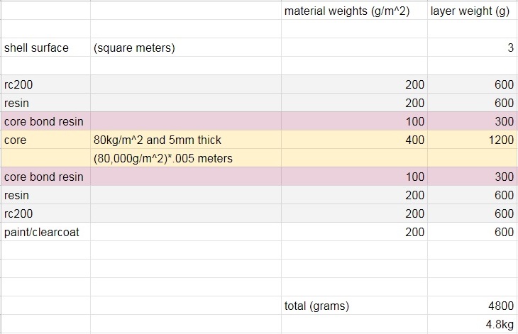
Assuming a 50% fiber fraction – hard to get less with only one ply and an aggressively (silly) small quantity of core-bonding resin… it works! I was sure it would get heavier, but it was close, and besides there was no time or money for anything fancier!
Once there was a plan for the layup, I thought about how to build a mold for the part. To get a decent surface without a ton of fairing compound (at this point a clear finish was still in the plan) a female mold was the ticket – but how to make one…

My first thought was to make a plug and then pull a quick female mold off using hand laid polyester or some leftover epoxy I had around. This would have made for a nice easy fairing process for the male plug and the composite tool would have had good vacuum integrity and would have been easy to handle. I didn’t do it this way, and in hindsight maybe it would have been a better choice. There just wasn’t much time and I didn’t want to spend any money that wasn’t necessary or waste any days. I went ahead and modeled a direct-built female mold:

The first major mistake was an error in communication. I got a model that was separated at the line where the nose meets the body. For some reason I thought the plan was to make the shell in two pieces – a “nose” part and a “tail” part. I drew the mold surface with a 6mm extension between these parts, where I planned to plant a plywood or aluminum rib that would form a flange in the nose and tail pieces. As it turned out this wasn’t necessary, and the final part was needed in one piece – so it was a 6mm longer piece than it should have been! Wasn’t a big deal here but in other situations it would have been a major problem! The lesson: always ask!
The shell surface was offset out for 1mm of fiberglass and primer that would go over the surface to seal the mold and give it vacuum integrity. I wanted to machine as little solid material as possible, so the back end would be strip-planked and only the compound-curved nose would be machined completely from blocks of MDF. The molds for the strip planking would fit together in what I call an “egg-crate” and the ends would have machined “bulkheads” (light blue) to make sure that the shape is right and it doesn’t get splayed out by the strip planking. Here’s the sketch:

The red perimeter on the left was a plant to form and in-turned flange. We didn’t end up doing that. The final part just got a single close-out ply of carbon wrapped around the edge and vacuum bagged.

Here are views of the solid blocks on the left and the egg-crate on the right. The U-shaped perimeter piece is just a single ply of MDF but it will help align everything. The rectangular bars at the bottom are 2×4″ aluminum box-beams to support the whole thing. I wanted to be able to move it around and figured I’d just build it on a low rolling table I had.
The station spacing for the egg-crate is very close – 200mm (8″-ish) because the strip planking is not very thick – 12mm/.5″ and I wanted to support it well. The egg-crate sheets were modeled off an offset piece of the surface that formed the volume of the strip planking. Strips butt into a center-line girder and the bottom of the upper U-shaped flange. You can see the center-line piece sticking up proud of the surfaces where the strips will lay:

Here is the egg-crate and the blocks laid down flat to be turned into sheet cutting patterns. Because the CNC router cutter leaves a radius in the corners, I have to add clearance features (“dog-bones” or “ears” to me!) to the inside shapes where the sheets notch together. In the above image on the upper right I am adding circles (12mm) to the corners and trimming away the original sides of the pocket. This leaves a flat bottom for indexing and clearance for the sheets to slot together without the radii interfering. If you look closely in the image below, you can see the clearance features on all the inside corners.

This is the cutting layout for the parts. Three sheets of material on the left will form the egg-crate pieces and the solid parts on the right will be machined from MDF. One mistake I made was to leave too little material on the bottom of the U-shaped egg-crate pieces. When I went to assemble it, one broke right at the bottom and they were very bendy in a way that was really not good.

The MDF was glued into blocks that were as high as the router could reasonable handle (with 3/4″ sheets, these were 4.5″ tall) and were machined to shape before gluing. I wanted to waste as little time roughing away MDF as possible! And here we are gluing up two of the blocks (there’s some perforated release film between the blocks) – one of the lower ones and one upper one. The green flow-mesh is all that is needed to spread vacuum all over.
Next up: Machining and Assembling the Mold!