EC! Home: Articles: Design for Composites: Basic Numbers and Calculations
Updated: 2/21/22
By: Chris
NOTE: This is still being proof-read, overhauled and is only half done. Definitely WIP!
This article is an overview of basic properties of composite laminates – and the individual lamina that make them up. It should help with discussing composite properties with both engineers and manufacturers and materials vendors.
First a bit about what makes composite materials special – and challenging. Metals and plastics are pretty much the same all the way through, and in any direction. Materials like this are called “homogeneous” because they’re made of the same stuff in a uniform way – and “isotropic” because no matter which way you push or pull, the properties are about the same. This makes things much easier to model and design. Composites, not so much!
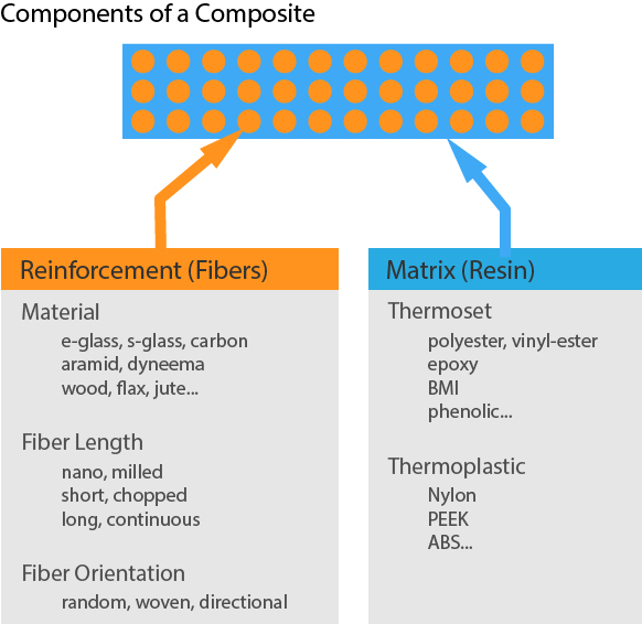
A “fiber reinforced polymer matrix composite” is a combination of two (or more) different materials. The first is a polymer matrix (plastic, resin, etc.) which on its own is uniform and isotropic. This polymer binds together a second non-uniform fiber reinforcement material. Because individual fibers are long skinny little cylinders, they bring a “directional” component to the composite’s properties. This directionality can make a composite much stronger in the direction of the fiber – while only about as strong as the resin in the other directions. This is called an “anisotropic” material. In most cases fiber reinforced composites are also “orthotropic” materials because there is a plane in which fiber runs in a variety of directions and a through-thickness axis normal to the fiber plane that hasn’t got fibers pointed that way.
The uniform component of the composite is called the “matrix” – the glue. The non-uniform stringy fiber stuff is called the “reinforcement.” You’ll see the words “matrix” and “reinforcement” used a lot. Feel free to think of it as “resin” and “fiber” if that sounds more obvious – because that’s what you’ll call them when building stuff.
Composite parts are usually made of several plies (layers) of reinforcement and resin – all squished together – and called a “laminate.” If each ply contains just fiber in one orientation (or orientation distribution) it is called a “lamina”. Many laminae pig-pile precisely up to make a laminate. Laminates are molded into parts. To “laminate” is also a verb for the act of assembling “laminae” into a “laminate” – fun huh?
So how do we talk about how much of what is where? The amount of fiber vs. the amount of resin in a given volume is important, as are the orientations of the fibers. You’d talk about a laminate having a certain volume of fiber and of resin, with the fiber pointing in a specified direction(s). Often these volumes are described in ratio or fraction form – which we’ll get into more below. To make it somewhat confusing, most of the time manufacturers and builders will deal with weight-based names for things. Weights of resin and fiber are much easier to measure, and materials are generally specified by weight. Engineering calculations are based on volumes of materials. So, you’ll see plenty of both volume fractions AND weight fractions.
Table of Contents
- Definitions
- Density
- Representative Volumes
- Rule of Mixtures
- Areal Weight
- Fiber Volume Fraction
- Laminate Thickness Estimates
- Fiber Directionality
- Quasi-Isotropic Laminates
- Symmetrical Laminates
- Balanced Laminates
- Balanced, Symmetrical AND Quasi-Isotropic!
- Resources
- Free or Cheap Analysis Tools
Definitions
Real quick, here are some of the terms used to describe the composite – and their definitions – and synonyms!
- Fiber: also known as “reinforcement” – like e-glass, carbon or flax.
- Resin: also known as “matrix” or “polymer matrix” – this is the “glue” that holds the fiber together. Most commonly epoxy, polyester or vinyl-ester for thermoset composites, though there are others. There are lots of thermoplastic matrix materials too.
- Composite: Fiber + Resin – usually all mixed together and squished.
- Laminate: A composite which a specific set of reinforcements of specific weights pointing in specific directions.
- Lamina: also known as a “ply” – one of the layers of a laminate, often made of material pointing in only one direction.
Density
Definition: Density is the mass per unit volume of a material.
In composites manufacturing, mass or weight is a typical way of describing parts. Only resin (before it cures!) is measured in volume – and then only sometimes. You say “That part takes 1.2 liters of resin”, but you wouldn’t usually say “There are 1.5kg of fiber and 1.2L of resin in that part.” If that 1.2L of resin weighs 1.5kg, you’d just say that part weighs 3kg! Skipping ahead, you could also say that the fiber weight fraction is 0.5, or 50%.
Mass divided by volume gives a measure of density. You will need to know the density of each of the components (resin, fiber, core) of your laminate to estimate its properties.
Examples: grams per cubic centimeter (g/cm^3), kg/m^3, lbs/ft^3, etc.
You’d say: “My laminate is 1.7 g per cubic centimeter.”
Densities of common materials that get mixed into composites:
- Carbon fiber: 1.75-2 g/cm^3
- E-glass: 2.55-2.6 g/cm^3
- S-glass: 2.45-2.5 g/cm^3
- Kevlar: 1.44 g/cm^3
- Polyester Resin: 1.1-1.5 g/cm^3
- Epoxy Resin: 1.2-1.45 g/cm^3
- Polyether ether ketone (PEEK): 1.3 g/cm^2
Representative Volumes
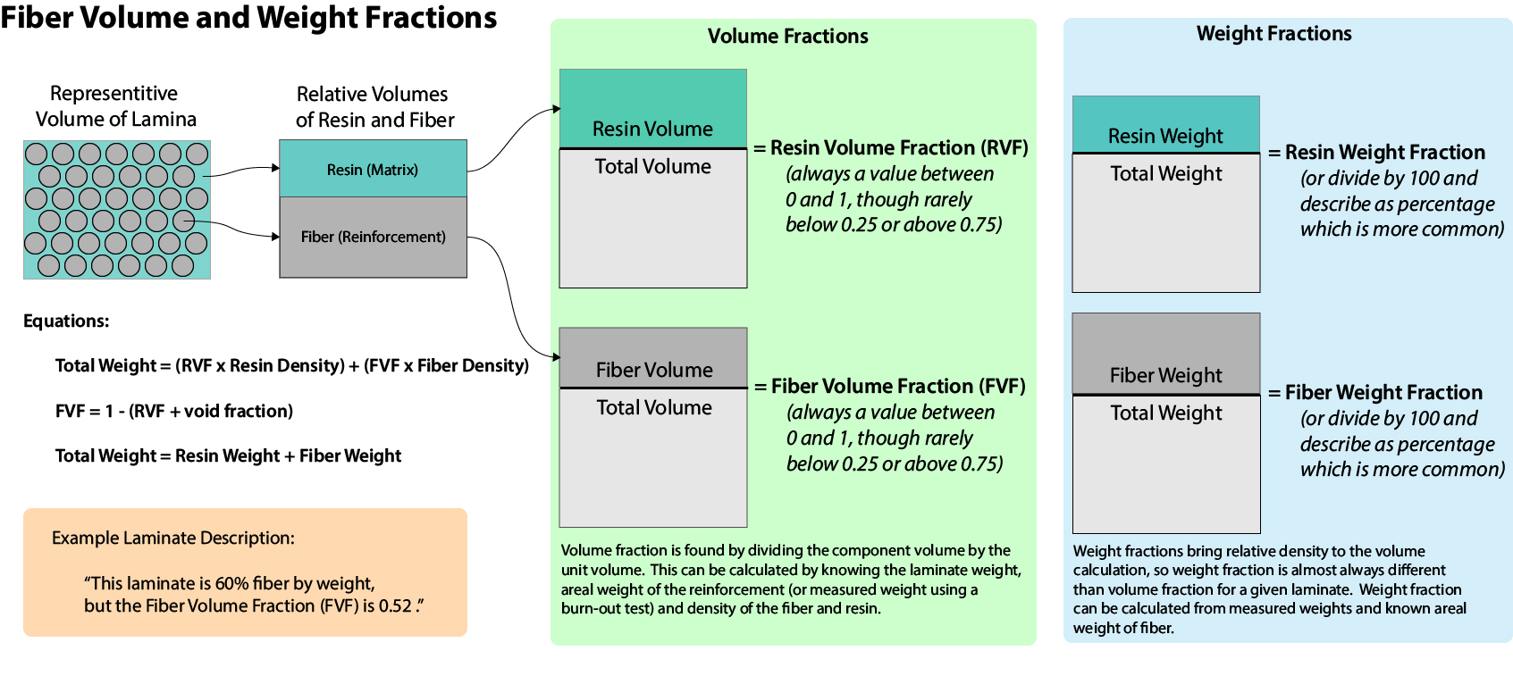
The properties of a composite laminate are dependent on both the properties of the fiber and the resin. The amount each contributes to the whole is largely based on its relative volume in the composite. If we divide a multi-ply composite into individual lamina – each representing a layer of the overall laminate, we can look at each lamina (aka “ply”) individually. For each lamina/ply we can look at a theoretical “representative volume” that includes typical proportions of fiber (“reinforcement”) and resin (“matrix”). The properties of these representative volumes are the fundamental building blocks of “micromechanics” – the analysis of mechanical properties of individual lamina.
The fiber makes up a certain fraction of the total lamina volume. By imagining all the fiber volume separate from all the resin volume, we can visualize the “fiber volume fraction”. Here it’s about 50/50. Combining the fiber and resin volumes into simpler rectangular “slabs” makes it easier to visualize the relative volumes. More on this later – for now it’s just good to know that mechanically, a composite is a weighted (by fiber and resin volume and by fiber direction) average of its parts.
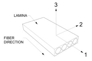
The composite’s mechanical properties depend on a combination of the properties of the fiber and the resin… and on the fiber orientation in each lamina. For analysis purposes, a representative volume of a lamina is typically given numbered orthogonal axes, independent of the larger laminate being analyzed. These are “1” in the fiber direction axis, “2” in the “across” direction and “3” in the “up” or transverse direction. You will see this notation used in laminate analysis calculations and each will have their own engineering constants for elastic modulus, shear modulus and Poisson’s ratio.
Rule of Mixtures
You can estimate the properties of a composite by multiplying the properties of the fiber and resin by their relative volumes. This is called a “rule of mixtures” approach, because it is based on the simple weighted mix of the constituents of the composite. This is typically done for each representative volume without regard for stacking order or ply orientation – these happen later on. The results you get this way are only approximations of the results you’d get if you measured a real representative laminate – but they are the way to start. It is important to validate your estimates with real-world material testing. Also – hire an experienced composite engineer!
Any given mechanical properties “X” of your fiber (X of fiber) and resin (X of resin) are multiplied by fiber volume fraction and resin volume fractions to approximate the properties of the ply’s representative volume as a whole. Here “X” is some parameter, for example: the modulus of elasticity (E).
By the “Rule of Mixtures” for each composite lamina:
X of composite = X of fiber * Fiber Volume Fraction + X of resin * Resin Volume Fraction
Fiber Volume Fraction + Resin Volume Fraction = 1
So each property contributes in proportion to its volume in the composite lamina. And each lamina contributes to the overall composite properties relative to its own volume, fiber orientation, mechanical properties and position in the “laminate stack.”
But to know these volume ratios of fiber and resin, we have to know how much actual space each takes up in the lamina. This can be hard to measure because the fibers are tiny, and the resin is all squished around all of them. But we know density from the resin datasheets and the fiber weight… and we may know the weight of the total laminate. How do we estimate the volumes?
First, we need to be able to describe the weight of fiber:
Areal Weight
Definition: Weight of a reinforcement material for a given area.
Example: My carbon woven reinforcement is 185 grams per square meter. (g/m^2)
Weight of Fiber = Areal Weight * Area of Ply
The areal weight is something that we know from the manufacturer of the reinforcement – or from our own weighing operations. Say we have a woven e-glass reinforcement that is 300 grams per square meter. That’s the areal weight: 300g / m^2!
Just a side note: areal weight as specified can be different from what you actually get – especially with heavier e-glass reinforcements. It is sold by weight after all! Up to 5 or 10% variation isn’t unknown – usually heavier than it should be. Carbon is usually closer to the as-specified weight. Just watch out though and check your material areal weight before you go assuming – a 10% weight error can be quite an “oops!”
Fiber Volume Fraction
As we see looking into the rule of mixtures approach for evaluating lamina – for engineering purposes it is important to know the relative volumes of a fiber and resin. A volume “sliced” will give you a knowable cross-sectional area. If you are talking about pressure, in “Newtons per Square Meter” or “Pounds per Square Inch” then you are discussing a pressure over an area. You wouldn’t say: “How strong is one kg of aluminum?” You might say what is the tensile strength of aluminum in N/cm^2. Or even, what is the tensile strength of this aluminum rod with a cross section of 1.6 cm^2. No different with composites!
So, what we need to calculate is the “Fiber Volume Fraction” (or “Fiber Volume Ratio”) of the lamina – or overall laminate. Usually, the fiber volume fraction is the one you’ll consider for engineering. The resin weight percentage is the more common metric used in manufacturing.
Definition: Fiber Volume Fraction is the ratio of fiber to resin by volume in a composite – or the percentage of fiber by volume in a lamina.
To calculate the volume of fiber we’ll need to know (or estimate) the weights and densities of the fiber and resin. Weights don’t need to be of anything specific – just of the same representative laminate for resin and fiber. If you have a chunk of uniform laminate of a measurable surface area that weighs 1000 grams, you can estimate the fiber weight. You either know the areal weight from data sheets or measuring dry fiber. You know the number of plies. If you were doing this in a lab, you might do a burn out test to remove the resin, weighing the (small) sample before and after the burnout. For now, we’ll imagine estimating with data sheet values – it smells better!
Weight of Composite = Weight of Fiber + Weight of Resin
And because we’re after the fiber volume fraction, we need the fiber weight fraction:
Fiber Weight Fraction (FWF) = Weight of Fiber / Weight of Composite
And from datasheets we know the densities of the fiber and the resin. With these we can calculate the density of the composite:
Density of Composite = (Weight of Fibers * Density of Fibers + Weight of Resin * Density of Resin) / Weight of Composite
And we can calculate the fraction of fiber volume:
Fiber Volume Fraction = (Density of Composite * Fiber Weight Fraction) / Density of Fibers
Our goal here is to be able to go back and forth between estimates of fiber volume fraction, and the fiber and resin weight ratios.
The theoretical maximum Fiber Volume Fraction (FVF) would be around 0.80 with packed unidirectional fibers of a small diameter. In cross-section little cylinders only pack so tight! This wouldn’t make a very useful composite though because there would be barely enough resin to hold it together. Practically the range is about 0.2 to 0.7 – here is a table of examples from the Materials Library videos:
[WORK IN PROGRESS]
| Material | Example | Fiber Density | Resin Density | FWF | FVF |
|---|---|---|---|---|---|
| Carbon Prepreg / Uni | Laminate Sample #4 | ||||
| Infused Carbon Triaxial / Epoxy Plate | Laminate Sample #30 | 1.85 | 1.25 | 0.65 | 0.58 |
| Infused Glass Plate | Laminate Sample #25 | ||||
| Wet Layup Glass | Laminate Sample #10 | ||||
| Infused Flax | N/A | ||||
| Hand Laid Chop / Polyester | |||||
| Infused Recycled Carbon / Epoxy Plate | Laminate Sample #47 | 1.8 | 1.25 | 0.24 | 0.18 |
Processing method matters too – pre-preg in an autoclave will have a higher volume fraction than the same materials hand laid with only a roller for compaction. Here are some typical fiber volume fractions for types of layups:
- Open Molded: 20-40%
- Vacuum-Bagged Wet Layup: 40-55%
- Infused: 40-55%
- Pre-preg: 50-70%
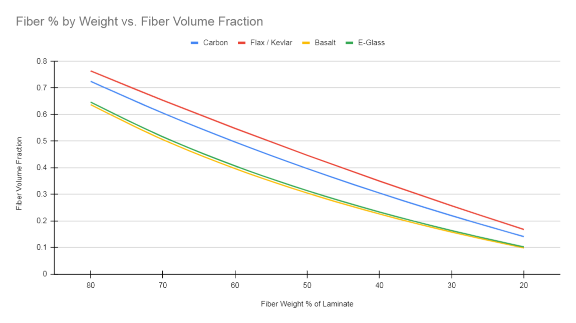
The densities matter a lot here, so the types of materials used will have a big effect on the relative fiber volume fractions. Carbon fibers are lower density than glass, so for a given fiber weight fraction – say 50% – the fiber volume fraction will be much higher for carbon (40%) than for e-glass (30%). So for the same fiber volume fraction, glass laminates will have a higher relative fiber content by weight. Carbon fibers are generally smaller in diameter than e-glass so the packing can be tighter – yielding a higher volume fraction.
Laminate Thickness
Knowing the approximate fiber volume fraction, laminate thickness can be estimated quite accurately. The higher the fiber volume fraction (FVF from now on!), the less resin is in the laminate, and the thinner it will be. In the chart below, see how 1000g of e-glass at a FVF of 0.5 is 0.1mm thinner than the same 1000g of material with a FVF of 0.4.
These are linear and with the exception on very thin laminates, should remain quite accurate. You could estimate that 10,000g of carbon at 0.5FVF would be 11mm thick. For infused and pre-preg carbon I have always used the “1000g per millimeter” rule for estimating – and it is usually pretty close. Expect variations for fabric types and processing.
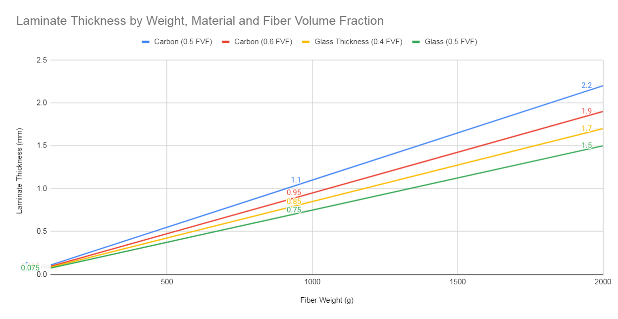
The carbon behaves the same way, but the chart shows higher overall FVF range for carbon.
Ply Parameters and Common Laminate Types
Fiber Directionality
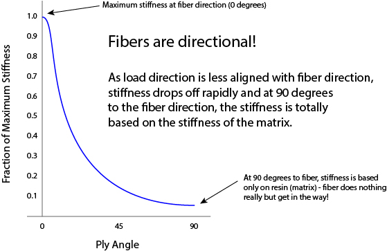
For a given ply, the properties of the composite depend on the direction of the fiber. In the fiber-direction, the composite will benefit greatly from the mechanical properties of the fiber. As the load direction deviates from the fiber direction, the fiber becomes less of a contributor. Eventually it’s just the resin matrix doing the work!
Imagine stiffness for example… here’s a look at how an imaginary fiber contributes to a laminate under load. As the load angle changes relative to the fiber axis, the fraction of potential stiffness drops way off – fast!
Stacking Order
When assembling lamina or plies of material into a laminate, the order in which they are applied is important – this is called the “stacking order”. Composite engineers typically deliver the builder a “laminate schedule” that is a list of the specific reinforcements, their areal weights, fiber orientations and the order in which they are layered. Layer 1 is typically the one closest to the tooling – which is the first applied.
Quasi-Isotropic Laminate – The “Black Metal” Method
Before we start into too many details, let’s look as a specific (and quite common) method of approximating an isotropic (in plane at least) material with an orthotropic one.
Definition: A laminate with equal weights of fiber pointing in each direction, limited usually to every 30, 45 or 60 degrees.
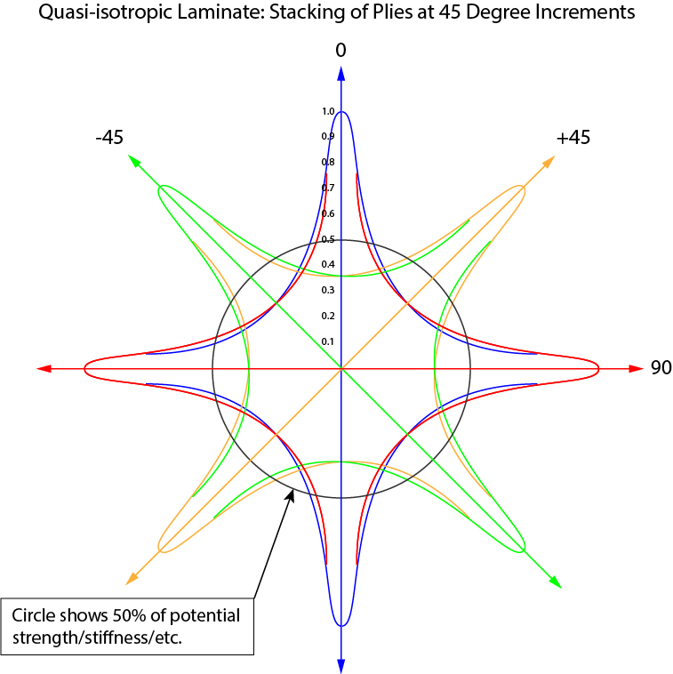
One of the great things about fiber reinforcements in composites is that you can point the fibers whichever way you want – focusing the mechanical properties of parts to align with loads. But sometimes you just want a composite panel that is the same strength in every direction – and this is actually kind of hard. The way engineers and designers typically achieve these “quasi-isotropic” laminates is by stacking plies that point in all directions equally. Because plies can’t be infinitely thin – there is no way to get exactly the same amount of fiber pointing in every single degree of laminate – so you approximate.
At 45 degree increments, the approximate fiber in each direction is enough to give a uniform “strength” (or stiffness, or whatever) in any direction. This graph is just the fiber directionality curve from above, mirrored about the axis and rotated every 45 degrees. You’ll see the 0,45-45,90 degree increments a lot – they are the building blocks of traditional “quad laminates” that make the vast majority of ply orientations you’ll come across.
Note that this is only quasi-isotropic in the plane of the laminate – “in-plane quasi-isotropic”. In the “z”, transverse or top-to-bottom direction, the laminate properties are based largely on the resin matrix, because there are (usually) no z-axis fibers.
Fiber “Clock”
Imagine that you are laying plies of material on a (12 hour) clock-face. Zero degree fiber orientation would be in the 6 to 12 orientation. 90 degrees would be from 9 to 3. You could just lay half the fiber at 0 degrees and half the fiber at 90 – and you’d have a laminate that had the same strength in both directions – but if you pulled on it in the 4:30 to 10:30 direction, you’d be applying load at 45 degrees to both stacks of fiber – and neither would have much ability to handle that load. The solution: apply your stacks at 45 degree increments instead of 90 degree increments! So now your clock has ¼ of the material each at 6 to 12, 9 to 3, 10:30 to 4:30, and 7:30 to 1:30. And now there is fiber relatively closely (22.5 degrees minimum) to any potential load direction – your “quasi-isotropic” (often abbreviated: “QI”) laminate from above. And we’d better translate that to fiber orientation angles and stop using a real clock-face for reference!
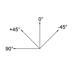
So as we discussed back there a bit, a basic quasi-isotropic (“quasi” because it is only an approximation in one plane – unlike say, aluminum) laminate could have an equal quantity of fiber in each 45 degree increment of the fiber “clock” – like this: 0,+45,90,-45.
If you can, the angle increment can be reduced to 30 degrees: 0,30,60,90,120,150 – or some other arbitrary number. The total panel thickness must be able to be made up of complete combinations of the “QI” stacks – because if you leave some out on the last stack, the laminate will have unequal quantities of fiber in all directions! And because stacking order matters and plies can have an overall impact on the stability of the laminate, next we’re doing to look at the idea of “balanced” and “symmetrical” laminates.
Laminate Notation
There is a convention for specifying laminate stacking orders and fiber orientations that looks like this: [0, -45, 0, 45, 0] – which means ply 1 is at “0”, ply 2 at -45, ply 3 at 0, ply 4 at +45 and ply 5 at 0. There are many additional details to this notation which you may want to look up. For now, when you see comma separated numbers like 0’s and 45’s in brackets like that – it may be a laminate description.
Symmetric Laminates
Definition: A laminate that is symmetrical about it’s neutral axis – having mirrored fiber weights and orientations.
Imagine that you are a very fastidious sandwich maker and that you always put cheese directly in the middle (the neutral axis) of your sandwiches. Moving out from the cheese you put the same ingredient on each side preserving symmetry about the mid-plane of cheese. So, if you add tomato to your sandwich next, there will be a tidy layer of tomato on either side of the “ply” of cheese. Next maybe some strips of neatly sliced pickle on either side of the tomato, and then lettuce on either side of the pickle – and finally two slices of bread – coated with equal layers of spread – so the spread meets the lettuce just-so.
This sandwich you have is “symmetrical” – every ingredient is symmetrical about the cheese in the middle. From the top we have a stacking sequence that looks like this:
- Bread – top
- Spread
- Lettuce
- Pickle
- Tomato
- Cheese – this is the neutral axis!
- Tomato
- Pickle
- Lettuce
- Spread
- Bread – bottom
Making this sandwich by starting with the cheese and trying to hold it all together would be a messy process. Being a very precise sandwich maker, you will have written this list down and will start from the bottom (bread) and add each layer carefully. Perhaps you will specify the thickness of the spread (in grams per square meter) and then the orientation of the pickles – zero of course!
So now that we are open to stacking our materials in a symmetrical way about the middle neutral axis, I will suggest that this type of stack is used a lot in designing composite laminates. Laminates like this are called “symmetrical” or “symmetric.” Back to the bracket notation for laminates – symmetry is easy to note. If I write: [0,-45,+45,90]S that “s” at the end (usually a subscript) means that the laminate is symmetrical and that the plies described are mirrored about the end with the “s”. So [0,-45,+45,90]S = [0,-45,+45,90,90,+45,-45,0] which makes things easier – especially when you start stacking a lot of plies! One more note on that – if you see a [0,90,0]T that “T” subscript means that what you’re seeing is the whole laminate. You can also group repeating sequences in parentheses with the number of times they repeat as a subscript. [0,(+45,-45)2,0] is the same as [0,+45,-45,+45,-45,0]
Turns out symmetry can be really important for making a composite that behaves gracefully and doesn’t get all warpy. As resins cure, they often shrink or change shape slightly. The fibers constrain this shape-change more in the direction they are pointed than in other directions. A laminate with just two plies of unidirectional fiber at 90 degrees to each other could very easily end up looking like a potato chip – it certainly wouldn’t remain flat! There are a bunch more of these “coupling” effects that become a big concern when designing laminates.
Here’s a video about what happens when your laminates aren’t symmetrical: Laminate Sample #34: Asymmetrical Prepreg Carbon
Keep in mind when considering symmetry, that woven satin fabrics (where warp and weft fiber go over one and under a bunch) are not symmetrical themselves, and will have more of one direction’s fiber toward one face of the fabric. Twills and plain-weaves don’t have this feature – they are reliably symmetrical.
Balanced Laminates
Definition: A laminate with each non-0 or 90 ply matched by an equal weight ply in the opposite orientation.
If each non-0- or 90-degree ply is matched by an equal ply in the “opposite” direction, the laminate would be “balanced”. In a balanced laminate all non-0- or 90-degree plies show up in (+) and (-) pairs!
Here’s a laminate that is NOT balanced – but is symmetrical:
- 200g Carbon Woven at 0/90
- 300g Carbon Unidirectional at +45 (this ply is matched by another just like itself, instead of one that is “opposite” or -45.)
- —neutral axis—
- 300g Carbon Unidirectional at +45
- 200g Carbon Woven at 0/90
Here is an example of another balanced laminate – with ply weights and fiber orientations but one that is NOT symmetrical (look at the 45s):
- 200g Carbon Woven at 0/90
- 300g Carbon Unidirectional at +45
- 300g Carbon Unidirectional at -45
- —neutral axis—
- 300g Carbon Unidirectional at +45
- 300g Carbon Unidirectional at -45
- 200g Carbon Woven at 0/90
Now by changing the stacking order slightly, it can be both:
- 200g Carbon Woven at 0/90
- 300g Carbon Unidirectional at +45
- 300g Carbon Unidirectional at -45
- —neutral axis—
- 300g Carbon Unidirectional at -45 (flipped these + and – 45 plies to be symmetrical about the neutral axis)
- 300g Carbon Unidirectional at +45
- 200g Carbon Woven at 0/90
We could write that last one like this: [CW200 0/90, CU300 +45, CU300 -45]s. See how the material types can go in-line with the laminate notation. There are lots of ways to do this, make sure the materials are officially named somewhere else if describing laminated this way.
This one may be balanced, symmetrical, or both – but it’s not quasi-isotropic – or even close! You have 600g of fiber in the +/-45-directions and 200g in the 0 and 90-directions.
When it comes to further analysis, the properties of balanced and symmetrical laminates make many of the calculations (and behaviors) significantly less involved. Unbalanced and asymmetric laminates will tend to bend out of the plane of the panel when loaded. These “coupling” issues can lead to extension bending and twisting – which require additional analysis. As you get into Classical Laminate Theory you will see that the ABD matrix ties the loads and strains by way of extension, bending and coupling. Balanced and symmetrical laminates allow you to “zero out” whole swaths of these parameters because in-plane stresses result only in in-plane deformation.
Balanced, Symmetrical, AND Quasi-Isotropic!
The ideal laminate for a quasi-isotropic (QI) plate will also be a balanced and symmetrical one. Sometimes this is challenging to meet given the need for finished thickness, ply thickness and number of plies in a QI stack. Each ply contributes to thickness and fiber weight and fiber orientation. Sometimes this can’t be reconciled into a panel that meets all the requirements. Often plain weave or twill-weave material can be used because it is itself both balanced and self-symmetrical because both warp and weft fibers average out around the neutral axis of the cloth. With unidirectional, it can be harder to manage because each ply only points one way. Some materials are not self-symmetrical like satin woven or stitched non-crimp fabrics – so if you’re fussy this is worth paying attention to…
It should be noted that there are alternatives to all these 45’s and 90s. Check out the “Double-double” concept: Composites design – Think composites (think-composites.com)
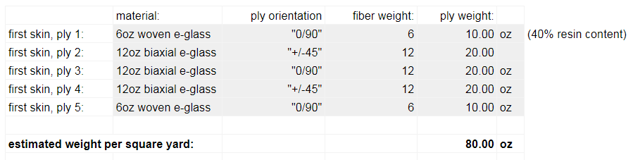
Here is an example from Laminate Sample #4 of a balanced, symmetrical and almost QI laminate. Because of the available fiber weights and thickness target, it isn’t quite QI – but it is balanced! If we had wanted a 3.2mm panel then it would have been ok to put another 200g woven in the middle there and have 800g of material in each of the four directions.
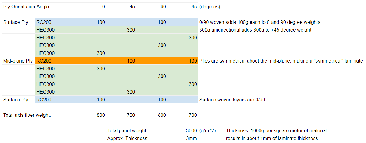
And here from Laminate Sample #19 – a fully balanced and QI laminate in e-glass that works out just right:
You can see the laminate appears symmetrical about ply 3. The weights of the “0/90” plies (6+12+6 = 24) are equal to the “+/-45” plies (12+12 = 24) so the laminate is both balanced and QI. You will grow concerned that stitched double-bias / biaxial is not itself symmetrical – so that requires either careful attention to ply flipping or lower standards of fussiness! Either way it’s not quite symmetrical because of that middle biaxial ply being not symmetrical. Only plain-weave and twill-weave cloth and unidirectional reinforcements are self-symmetrical.

For an example of QI and Balanced Laminates, check out this video:
Design and Engineering
Composite engineering is (I’m told) difficult. There are lots of variables. Compared to a metal, plastic or other isotropic material, there is a lot to pay attention to and a lot that can go wrong without the possibility being obvious beforehand. The big picture follows the same process you’d use to design pretty much anything – start with broad strokes requirements and work around the spiral making decisions as you go and trying to avoid throwing away too much already “completed” work. With composites, the decisions are similar, but there is more to keep track of at the geometry, assembly, structure level.
Generally the workflow will go:
1. Estimate using simplified methods, check if things are close enough to give you confidence that the approach is valid. Do you really want to use composite materials or will something simpler, cheaper, easier be ok? See the “Pretend Metal” section below.
2. Engineering modeling and calculations of the simplified structure, laminate, and geometry. This would be a more granular look at the parts, assemblies and complete structures using formulaic engineering tools – “hand calcs”. Developing laminates using classical laminate theory to firm up guesses and validate the overall structural approach. A this point, material samples should be made and evaluated and calculated properties validated to whatever level makes you feel comfortable.
3. FEA, detailed engineering and more thorough material and manufacturing process testing. FEA is the go-to for most composite engineering beyond a level of complexity that can be generalized comfortably as “beams, plates, etc” and evaluated with common formulas. Even then, somebody who knows their way around composites FEA can model simple scenarios relatively easily. Having that “visual” into the structural situation is so valuable for building intuition and making changes is so relatively easy that FEA is done probably more than is strictly necessary. It is easy to mess up (how do I know, you ask?) and there are lots of ways to make is look like you did it right but have major gaps or mistakes that aren’t obvious. It really pays to have experienced engineers do this kind of work (or supervise it) and to make sure it is backed up by enough simplified structural calculations to avoid major oversights.
Caution: I am not a real engineer and am new to this too, so if you really want to learn this, have a look at some of the books in the appendix at the end of this article. And if you are an expert and see that I have oversimplified (too much) or made a mistake – please call me on it!
The “Pretend Metal” Method
The simplest way to evaluate composite structures is to generalize the laminated material into something that behaves isotropic-ish in the x and y directions and just ignore the fact that it is definitely not the same in the “through thickness” direction. By assuming that a composite laminate is quasi-isotropic, balanced and symmetrical, you can treat it like metal and mostly be able to make useful assumptions about its strength and stiffness. For example, you could assume a QI carbon/epoxy laminate has an elastic modulus (E) in both the longitudinal and transverse (or any other in-plane) direction of about 60 GPa (8.7msi) and maybe a ultimate tensile strength of 600 MPa (87,000 psi). It’s not going to tell you everything but you can say “yeah, kind of like 6061 aluminum but about half the weight” – which is maybe enough to get you feeling like composites are worth the hassle. Similar things can be done for unidirectional laminates, like stringer caps and other situations where composites get awesome.
Classical Laminate Theory
As things get more serious, let’s look at a framework for estimating the properties of an actual laminate made of actual materials. This process is called “classical laminate theory / analysis” and involves several bundles of calculation and analysis steps. This is often a first step in evaluating a composite laminate, often followed up with FEA and more specific detailed engineering work. With orthotropic materials, there isn’t a simple mapping of stresses to strains as there would be with isotropic materials. It’s kind of messy: you have fibers in varying weights pointed in various directions at different thicknesses through the laminate. This approach generates a way to calculate strains from stresses or stresses from strains – but it takes a bit of work to manage all those plies, thicknesses, and angles!
The first step – called “micromechanics” – is to assemble mechanical properties of constituent fibers and resins into lamina with fiber volume fractions and mechanical properties based on a rule-of-mixtures (weighted average) approach. You can also start with measured properties of a laminate that come from coupon testing, from a book, or some numbers you found on the internet. See below for some sets of typical properties of unidirectional lamina with different resins and reinforcements.
From there you’ll move into “macro mechanics” and use your laminate stacking order and ply orientations to assemble matrices (Q,S and their inverses) that tie together the various parameters and allow them to be more easily manipulated. These matrices (and their inverses) will allow you to translate lamina from their own (1,2,3) space to the (x,y,z) space of the laminate. Once all the plies are translated into the laminate coordinate system, they can be combined into a larger matrix (ABD matrix) that assembles all the laminate properties and allows a large number of linear combinations to be manipulated and handled relatively easily – at least by a computer!
Once you have this whole ABD matrix (and its inverse), it allows you to map a vector of stresses to the resulting strains, or back the other way in each of the three x,y,z directions specific to the laminate. It also lets you evaluate the global properties of the laminate, with the contributions of each ply added together. A set of stresses or strains can be mapped back to each individual ply by reversing the rotations that assembled them in the first place. This allows you to analyze each ply against a set of failure criteria and estimate at what loading condition each will fail and how it will impact the rest of the composite.
FEA
[COMING SOME DAY]
Numbers
Before we do math, let’s get some numbers together! Here is a list of the key number values you’ll need for any laminate you’re going to analyze. Don’t trust these – they’re assembled by me from junk found all over. But for the purposes of estimation, they may be useful:
| Material | CSM* / Polyester | E-Glass / Epoxy | S-Glass Epoxy | Kevlar / Epoxy | Std. Mod. Carbon/ Epoxy | Int. Mod. Carbon / Epoxy | |||
|---|---|---|---|---|---|---|---|---|---|
| Symbol | Units | ||||||||
| Density | ρ | g/cc | 1.45 | 2 | 2 | 1.45 | 1.6 | 1.55 | |
| Fiber Volume Fraction | Vf | 0.25 | 55 | 60 | 0.55 | 0.55 | 0.6 | ||
| Typical Manufacturing Process | Open Molding / Choper Gun | Vacuum Bagged Wet / Infusion / Prepreg | Infusion / Prepreg | Infusion / Prepreg | Infusion / Prepreg (Oven/Autoclave) | Prepreg (Autoclave) | |||
| Elasticity | Longitudinal Modulus | E₁ | GPa | 6 | 42 | 55 | 75 | 130 | 150 |
| Transverse Modulus | E₂ | GPa | 6 | 10 | 16 | 5 | 10 | 9 | |
| In-Plane Poisson’s Ratio | v₁₂ | 0.32 | 0.22 | 0.26 | 0.32 | 0.3 | 0.34 | ||
| Through-Thickness Poisson’s Ratio | v₂₃ | 0.3 | 0.4 | ||||||
| In-Plane Shear Modulus | G₁₂ | GPa | 1.5 | 5 | 7.5 | 2 | 5 | 5 | |
| Strengths | Longitudinal Tensile Strength | F₁t | MPa | 75 | 1050 | 1800 | 1600 | 1750 | 2400 |
| Longitudinal Compressive Strength | F₁c | MPa | 150 | 600 | 690 | 340 | 900 | 1250 | |
| Transverse Tensile Strength | F₂t | MPa | 75 | 35 | 40 | 30 | 30 | 80 | |
| Transverse Compressive Strength | F₂c | MPa | 150 | 125 | 140 | 135 | 200 | 280 | |
| In-Plane Shear Strength | F₆ (F₁₂) | MPa | 10 | 60 | 70 | 40 | 100 | 150 | |
| Coefficients of Expansion | Longitudianl CTE | α₁ | μm/m/℃ | 6 | 5 | 2 | -2 | -1 | -5 |
| Transverse CTE | α₂ | μm/m/℃ | 20 | 25 | 6 | 60 | 25 | 25 | |
| Longitudinal CME | β₁ | m/m/kg/kg | 0 | 0.01 | 0.01 | 0.003 | |||
| Transverse CME | β₂ | m/m/kg/kg | 0.2 | 0.2 | 0.3 | 0.5 |
*The CSM/Polyester numbers are suspect – remember that chopped strand mat (CSM) is an “all-directions” reinforcement. Best data I could find from Robert Scott, Fiberglass Boat Design and Construction 2nd Ed.
See list of Resources below – Barbero, Jones and Coburn’s books all have excellent tables of data on many materials with much more detail than is available here.
More to Come!
My goal is to continue with a basic description of the classical laminate theory approach, with a minimum of mathy looking stuff that most of us have forgotten. I’d definitely have to get a book out to invert a matrix these days! Fortunately, spreadsheet programs do this with almost zero effort!
Resources
- Barbero: Introduction to Composite Materials Design – 3rd edition also has a workbook, which is very useful!
- Jones: Mechanics Of Composite Materials
- Ma and Elkin: Sandwich Structural Composites: Theory and Practice
- Agarwal, Broutman, Chandrashekhara: Analysis and Performance of Fiber Composites
- Tsai, Double-Double 2nd Edition – (think-composites.com)
- Greene: Marine Composites
- Abbott Aerospace: Analysis and Design of Composite and Metallic Flight Vehicle Structures
- Dr Todd Coburn’s YouTube – Professor/YouTuber – Lots of good composites/engineering videos – also has a great Composite Strength Handbook
- Dr Vinay Goyal’s YouTube – Professor/YouTuber – Aerospace structures, FEA, composites videos
- ASM Handbook Volume 21: Composites
- University of Cambridge: Mechanics of Fibre-reinforced Composites
- Digital Engineering: FEA and Composites, Part 1
- Digital Engineering: FEA and Composites, Part 2
Cheap or Free Analysis Tools
- VECTORPLY: VectorLam
- The Laminator: Classical Analysis of Composite Laminates – $30 – with a simple interface and report format – actively supported.
- ESP Composites
- ABD Composites: INTERACTIVE COMPOSITE LAMINATE CALCULATOR – not sure if this is supported…
- CalculiX FEA: A Free Software Three-Dimensional Structural Finite Element Program
- PrePoMax: Open-source pre and post-processor for the Calculix FEM solver