[WORK IN PROGRESS! You will notice that there are no (few) graphics and it badly needs editing and trimming. I’m working on it!]
This article is supposed to be a get-ya-up-to-speed on the vacuum infusion process for laminating composite parts. The focus is on disposable-bag infusion with polyester, vinyl-ester or epoxy. It isn’t comprehensive but it contains much of what you’ll need to know to be successful. You will have mistakes. You will have screw-ups. You will have to throw stuff out. My hope is that all those things will happen much less if you read this article!
As with all composite processes, control is the goal. The better sorted your process and the more you understand why you’re doing things the better. With preparation, it can always be made easier, more obvious and less stressful!
For a quick look at a bunch of different simple infusions, check out the “Infused Samples” section of the Laminate Sample Index.
You may also find these other articles helpful:
Table of Contents
[coming!]
What is Vacuum Infusion?
Vacuum Infusion (or “Resin Infusion”) is a process of combining fiber and resin that uses atmospheric pressure to drive resin through a stack of dry reinforcement materials that are under vacuum. It’s pretty neat to watch – resin just flows into and through the stack of fiber wetting it out as it goes. The fiber is under a vacuum bag and so everything is already well compacted and pressed against the mold. When the resin has completely filled the part, you clamp off the resin feed lines and let it cure. The resulting part is well compacted and should have a very low void content – no air bubbles – and a nice pinhole-free surface. When all goes well it’s a beautiful thing, but the learning curve is steep, and even small mistakes can result in scrapping the whole part!
For the last thirty years, vacuum infusion has steadily become a more standard composite process. It fits in the middle between pre-preg on the higher end and hand layup on the lower. Infusion has been steadily stealing ground from both as more fabricators grow comfortable with the process and part quality and efficiency continue to improve. Even aircraft components – long the domain of pre-pregs and autoclaves – are increasingly infused as large manufacturers look for ways to decrease costs and shorten the overall cycle time.
Let’s have a look at the trade-offs:
The big benefits of vacuum infusion are:
- Layup is done with dry fiber and tailoring and ply layout is not constrained by resin gel time. So you can kit it out and make it nice!
- No autoclave or oven! (except to post-cure)
- High quality laminates with low void content and excellent core-bonding.
- Clean, worker-friendly layup process. Only mix resin once and don’t get it on you.
- Consistent part-to-part quality and repeatable weight. Not as good as pre-preg but better than hand layup.
- Ability to laminate both skins and core, and potentially stringers and other structures in one shot.
- Production-friendly for moderate volumes. Easy to control once you have a system. It is very trainable, and continuously- improve-able!
At the same time, there are some drawbacks:
- Mistakes can be catastrophic – easy to lose parts if the infusion goes off the rails.
- Requires some fussy bagging work with lots of details.
- Cosmetics can be a challenge for highly finished parts – fiber and core print, shrinkage.
- Not suitable for high-volume production.
- Not compatible with honeycomb cores.
- Can be heavier than bagged wet-layup, but only because a wet-bagged core uses lighter filled resin (or air) to bond core.
- Heavy unidirectional reinforcements can be problematic to infuse.
- Lots of waste! Holy crap what a lot of trash – but not much worse than other similar processes.
Overall, vacuum infusion is a desirable way to build composite parts. It has a lot of the benefits of pre-preg in terms of detailed layups and thick laminates, but it’s cheaper and faster and doesn’t require an oven or autoclave. Compared to open molded or vacuum bagged wet layup, it is much cleaner and more consistent – and the resulting laminates have a much lower void content. After decades of steady development, vacuum infusion is a mature technology with well established processes, support products and equipment. One problem – sometimes it’s hard to get it to actually work. This article is here to help you through the learning curve!
When to Infuse
Vacuum infusion is the go-to mid range process for composites manufacturing. It’s easier to ask why NOT to infuse! So that’s what I’m going to do. The reasons not to infuse are:
- It’s too slow…
- or too expensive…
- or too heavy.
- You’re building a one-off part and infusion-capable tooling isn’t worth the cost…
- or you have to use existing tooling that wasn’t designed for infusion.
If it’s too slow, you need compression molding, RTM or maybe even some other technology like heavy gauge thermoforming. If it’s too expensive, then you should look at hand layup, spray-up or maybe bagged wet layup – but probably not. If it’s too heavy then maybe you need to look into pre-pregs – you’ll also get better unidirectional laminate performance and the option to use honeycomb cores – but you’ll pay! You can sometimes save weight with a careful bagged wet-layup especially with epoxy and cored parts. Core bonding with filled resin is lighter than infusing all the joints, kerfs and bleed holes with unfilled resin.
One of the great things about vacuum infusion is that it can be used with most common thermoset resins. So polyester is totally an option if you need cheap gel-coated parts. Epoxy is easy if you need high performance. Some of the processing techniques change a little from one resin system to another, but fundamentally it is the same. In theory your team will be able to do vinyl-ester one day and epoxy the next.
In deciding between hand layup/open molding vs. infusion, one deciding factor will be the need for core. Using foam core, balsa, or Coremat with open molding (vacuum bag or no) is totally doable, but it’s messy and not very repeatable. You’ll probably have more re-work and it will certainly be less pleasant for your team. With infusion, the option of using core becomes much easier for two reasons: First, you can use standard contour-cut or flat-sheet core without the need to make a separate core bonding putty. The same resin that fills the reinforcement fibers will bond the core – and in only one operation. Second, you have the option of simplifying the layup by using a core that also works as a flow-media. Foam cores with flow grooves and perforations are very effective at moving resin through a laminate. Infusion-specific cores like Lantor Soric add lighter-weight thickness while helping resin flow.
Another important consideration is tooling. Vacuum infusion requires pretty nice molds – ideally with wide flanges. If you are starting from scratch, it isn’t hard to make molds that are great for infusion, but you need to consider some key details. If you have older molds that have been used for open molding or bagged wet layup, it may take some work to make them ready for infusion – at least if you want the infusion setup to be easy.
Unless you have a compelling reason not to infuse your composite part, it is probably worth a serious look. Given the decreased exposure to nasty resins, the increased laminate performance and the opportunity to build nice cored parts all at once without dividing the lamination into several stages – there’s a lot that’s good about infusion!
Process Preview: The Steps
This article is long, and to introduce the topic, I’m going to go over the basic process real quick so you will have an idea what’s going on later. If you want to just see an example, here’s a video that shows the process used to make a thick(ish) carbon plate:

This one is just a big stack of carbon infused with a surface flow media. Check out some of the other infused samples too.
Laminate Sample #30: 6mm (0.25″) Infused Carbon “Tooling” Plate
Infusion is more like pre-preg in terms of order of operations because you have all the time you need to lay out your materials in the tooling. The material is all cut and fit dry. You only turn it into a part when everything is ready. This changes the way you organize yourself in a big way compared to open molding and hand layup where you’re always racing against the gel time of the resin. It gives you lots of freedom to do careful layup of larger and more complex parts. It’s also easier on the bodies of the people doing the work, because there is only the one-time exposure to the resin during a part construction – and then it’s only in buckets and hoses, not all over!
To start an infusion, the first step is to prepare the mold. Just like open molding, you have to apply a release system and any in-mold coatings you plan to use.
For polyester and vinyl-ester resins, gelcoat works the same way, and you may also want to apply a skin-coat to either the whole or to specific zones of your surface – depending on laminate thickness and cosmetic requirements. Usually a skin coat with 1.5-3oz / 50-90mils of mat and a non-waxed laminating resin will work fine if you plan to make the part from polyester or vinyl-ester resin – within a relatively short window of time. Avoid too many overlaps in your skin coat as the shrinkage can lead to pre-release. When this happens and you then infuse, the infusion resin can run between the part and the mold making a mess. “Print-blockers” and surfacing products can also be used to improve part cosmetics but are co-infused with the part instead of pre-laminated.
When you’re ready to lay up the outer (mold side) skin, you start dropping plies dry and sticking them carefully to the mold (or the gelcoat or skincoat) with a minimal quantity of spray adhesive. Dry fiber tailoring needs to be as careful as with wet material – or more so – because dry material is less likely to slide into slip-jointed areas than goopy resin soaked material. Your bag won’t just press out dry slip joints unless they are carefully made and with minimal (ideally no) spray adhesive in the slip joint zones. It is a good idea to press or roll inside corners with a roller/rub stick/dibber/butt of scissors on heavy layers of material to break in the slip-joints.
You do know about slip joints… right? If not – check out: Slip Joints and Why You NEED Them!
Assuming that you are using core, this gets loaded after the first skin is down. The core needs to be perforated (and maybe grooved) to allow resin to flow from the bag-side skin through the core to the mold-side skin. Balsa and foam need to be contour cut for curved areas, though carefully thermoformed core works ok if you’re trying to save weight. Just make sure you drill the through-holes after you heat and form the foam or they’ll close up on one side and not let resin through! Remember core-tapers and ramps should be smooth and well-considered – abrupt edges of cores can become “race-tracks” for resin as the part infuses.
The other big thing to worry about with core is the quality of the fit! If the sheets have big gaps between them then you will end up with huge pools of resin in there. This is heavy, wasteful, can cause racetracking, and impact cosmetics on the part surface if the core joints print through. All those bad things can be headed off with tight core fits – CNC cut kits and filling gaps with strips of core can really help. If you find yourself always fixing one area of the core kit – make a change to the master patterns!
There are also some infusion-specific cores (like Lantor Soric) that aren’t super light or thick but can bulk up an otherwise heavy single skin laminate and provide a useful “interlaminar” flow media at the same time.
Once the core is fit, the second skin goes on in the same manner as the first, with careful tailoring and a minimum of spray adhesive. When all the material is in place, a peel ply can be applied, again with slip joints and minimal laps. Light spray adhesive helps to hold it in place. If the part is made with a B-side tool (VARTM, or Light RTM style) this can either go right over the laminate or some peel ply may be used in areas where there will be secondary bonding. Reusable bags (silicone usually) can be used with or without peel ply and resin feed and vacuum manifolds are usually built into the bag.
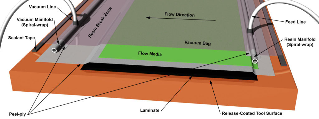
In most cases with consumable bags a surface flow media goes on next – this can be an infusion mesh, “shade cloth” or a combination product like Compoflex. The infusion feed layout (spiral wrap, elevated feed, Enkafusion, etc.) is placed to supply resin to the flow media. This layout is often the source of much head-scratching and for high-stakes projects it is common to use simulation software to test a variety of options. Adequate resin breaks and vacuum side manifolds (spiral wrap, flow mesh, etc.) are positioned to keep vacuum pressure on the part and take up any excess resin. Then you (very carefully) fit a vacuum bag and make neat, well-sealed bag penetrations wherever hoses go through.
Once your bag is pulled down you carefully measure the vacuum (with a digital gauge ideally) and make sure there are pleats and extra vacuum-bag where needed – and no bridging! It’s fair game to roll inside corners carefully with a smooth roller. A drop test confirms (or not) that you have a good well-sealed bag and that there are no major leaks. If you have the luxury of time, it’s good to let the dry stack sit under vacuum for a few hours – or overnight – to remove moisture and trapped air that takes a while to get out of cores and tightly woven fabrics.
When you’re ready to “shoot” the infusion, you’ll get your resin mixed and degassed (if you choose) and split up into buckets around the part where the feed lines go in. Depending on your part size and feed layout, you may be staggering the feed – opening the feed lines one after the other as the resin front progresses across the part. Everything goes smoothly and no islands of dry material get trapped and the resin doesn’t “racetrack” along any shortcuts.
You clamp off your resin feed when the part is completely infused and make any changes to the vacuum level that may be part of your plan. Temperature should ideally stay the same until the resin gels, at which point it may be increased to enhance cross-linking density. Your part is demolded when the resin is cured – and hopefully it looks awesome and doesn’t have any defects!
So that’s an overview. There are plenty of details to control here – but let’s do a little theory first.
Theory
Vacuum infusion works because resin flows from a place of high pressure (outside the bag – in the bucket) to a place of low pressure – inside the bag. You have used a vacuum pump to suck (almost) all the air out from under your bag. The atmosphere is pushing down at approximately 14psi all over you, your bag and the open top of your resin pot. The atmosphere is pushing down on the surface of the resin in your feed bucket – like a big syringe plunger.
You could get even more pressure on your feed if you put the resin in a pressure pot and jacked up the pressure – driving the resin into the bag. This is how RTM works – it uses much more pressure than the atmosphere can provide but it’s fundamentally the same idea. But that would turn your vacuum bags into resin-filled balloons – and high pressure resin isn’t something to get mixed up in if you don’t need to!
[Pressure graphic]
So it’s all a game of differential pressure, dry-stack permeability, resin viscosity, flow distance and cross-section area. Darcy’s Law shows the relationships between these parameters and is the basic framework for what is happening with infusion.
It pretty much says: Flow Rate = Pressure Gradient * ((Permeability * Cross Section) / Viscosity)
It isn’t as useful for actual calculation as it is to illustrate the connections between the parameters involved. You can try calculating but it will be hard to come up with a coefficient for permeability for a laminate stack – but it can be determined experimentally.
[Darcy’s Law graphic]
When you have a vacuum in a volume of space, in theory there isn’t any air in there. Realistically, there will still be plenty of air molecules – just way way fewer than there would be normally. So when you make a vacuum bag over your dry reinforcement fibers and core, and then pull a really good vacuum, the spaces between the fibers and inside the core are actually full of nothing! This is very strange to think about – but you could empty the air out of a vacuum chamber and still have volume in there right? Or in outer-space: there’s actual spatial volume between those stars but no “air” in it – just the occasional asteroid, comet or… spacecraft.
When you finally open up the resin feed lines, the resin isn’t really displacing air, it’s filling a void in which there wasn’t any air. Realistically, there is still a small quantity of air and vapor and other gasses in there, but not very much. Even a modest vacuum pump will be able to remove a vast majority of the air molecules if given some time to do it. So the better your vacuum, and the longer you hold it on the dry stack, the more air is going to be gone, and the less will be able to stay in there when your resin front comes rumbling through filling up the void.
When your resin is introduced, it is going to “want” to take as easy a route through the materials as possible to fill all the empty areas of low pressure. If you leave easy ways for it to shoot through and clog up the vacuum outlets, it will. This is called “race-tracking”. You want to control the flow of resin through your laminate stack so that it progresses evenly and at a speed that easily fills the part before the resin gels, but not so fast that it traps any remaining air. “Overrunning” air by feeding too fast can be a problem with low-viscosity resin (and higher temperatures) so you want to plan on a steady feed rate that matches the permeability of the laminate stack and the gel time of the resin.
Speaking of “permeability”… as the vacuum compresses the dry stack, the gaps between the reinforcement fibers are squished down. Fiber diameter is important because larger fibers like e-glass will have larger gaps between them as they pack in tight. Smaller diameter fibers like carbon pack down very closely and can leave very little room for resin to flow through.
[graphic of large and small fiber packing]
The type of fabric is important too – wovens and stitched fabrics have natural channels for resin to flow. Large clumps of unidirectional fibers pack very tight (think: handful of spaghetti) and it can be hard to get resin to flow through and completely wet out the reinforcements. Many manufacturers sell infusion specific reinforcements. These can have extra stitching, wider spaced fiber-bundles or built-in flow-media between plies. If you need to infuse very large “planks” of unidirectional material, it may be necessary to use a specially designed reinforcement with some infusion-friendly features – or just use pre-preg!
So your big goals with infusion are:
- Maximize the pressure differential between the cavity (under your bag) and the atmospheric pressure.
- Remove as much air and vapor from the dry stack under your bag as possible. High vacuum levels and heat help with this.
- Don’t have any leaks! Once the resin is in, keep air out.
- Control the way your resin flows through the dry stack of materials – it should be systematic and orderly!
- Fill the part before the resin starts to cure.
If you do all these things then you will be on your way to a successful infusion process. There are plenty of other details that can mess you up – but these are the big things to keep your eye on. Not nailing one of these down will give you endless headaches!
Terminology
There are a few terms that I will use here to discuss infusion. Here I’m going to give rough definitions:
- Vacuum Side: This is the “end” of your infusion where the vacuum hoses attach to the part and lead to catch pots and then to your pump. This could be a perimeter or an edge with a resin break – or somewhere in the middle.
- Feed Side: This “end” is where the resin is let into the part. Often this is a manifold (spiral wrap, flow mesh, etc.) connected by hose(s) to the resin pot.
- Feed Distance: The distance along the part surface from a point on the feed side to a point on the vacuum side. The distance your resin must flow to fill the part.
- Vacuum Level: What I mean here is the gauge level of vacuum – or how much there is no air in the part! High vacuum is what you get when there are no leaks in your bag and you have a pump that really pulls (ok, “sucks!”)
- Viscosity: The viscosity of the resin is an important parameter for infusion. Viscosity generally decreases with temperature. Think of low viscosity as like water, high viscosity as like syrup!
- Permeability: This is a measure of how easily resin flows through your laminate. Fiber size and fabric style have a big impact on how permeable the laminate is. High permeability means that resin flows through easily.
- Pressure Gradient: The pressure difference between the feed side and the vacuum side as experienced by the laminate.
- Resin Front: The leading edge of the line of resin as it fills a part. Usually a froth of bubbles as the resin displaces what air is left in the part.
- Gel Time: The time it takes for the resin to start curing and becoming hard. Your infusion needs to be done by the time the resin “gels” because hard resin doesn’t flow anymore!
- Dry Stack: The bundle of materials (reinforcements, core, process material) under the bag before it is infused.
So now that we’ve gone over the overall plan, it’s time to discuss specific considerations and then dive into the steps of the process!
Tooling for Infusion
Tooling for infusion needs to be airtight. That’s the big thing – no leaks! Your vacuum is everything in an infusion and if the mold leaks you’ll be in trouble. You need to vacuum test any new tool and make sure that it can be pulled to a very high vacuum, and that it has good drop test performance. See more about Drop Tests below. For molds with multiple parts, a good gasket system is key – and it needs to interface well with the bag to complete the seal. In a pinch you can bag the flanges together but this is really only good for one-offs or as a last-ditch effort.
Find your leaks and problem areas before you load the mold up with materials. It will also help to have a benchmark for your mold, your bagging material and your vacuum system when doing the drop tests before infusing actual parts.
It also has got to have a wide enough flange for all the vacuum bagging, vacuum plumbing and resin break features you’re going to need. For disposable bags or silicone re-usable bags, you’re going to want about 10″-12″ of flange beyond the part. You can do it with less, but it will always be a battle! And for series production, the last thing you or your team wants is a battle on every part. Paying for 6″ of extra flange is the cheapest choice there is compared to perpetual frustration and wasted time!
You might also want to make provisions for heating production molds. Infusion is a game best played warm! Resin flows better (lower viscosity) and cures faster at higher temperature. Moisture issues will be reduced by dry-debulking your laminate stack at a higher temperature before the resin is introduced. There really aren’t any problems that heat creates up to a reasonable point, but cold will create plenty of headaches. The upper limit should be the comfort level of the people working on the infusion and (maybe) the cost of extra energy. Heat matters more for epoxy infusion, where viscosity is much higher.
Generally speaking you want your tooling to be made of similar materials to your parts. The coefficients of thermal expansion should be similar, especially if there will be elevated cure temperatures or post-cures needed. Carbon parts can be made in fiberglass tools but you’ll want to be mindful that in a post-cure there could be movement with larger parts. You can totally make tooling for epoxy parts out of polyester or vinyl-ester tooling resin – and tooling gelcoat will be a nice surface to work with – but keep in mind the service and “exotherm spike” temperatures. You don’t want tools to distort or crack because you pushed them too hard on the thermal front!
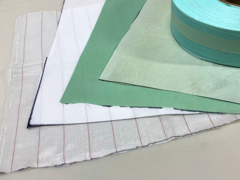
Infusion-Specific Reinforcements
Infusion is a very common process in the composites industry and material manufacturers supply all kinds of infusion-specific materials. This is great because these materials are designed specifically to make infusion easier! One of the key features of infusion-friendly reinforcements is permeability. Large fiber bundles and bulk unidirectional tows are hard to infuse reliably. By engineering the reinforcements to include smaller fiber tows, more stitching and often built-in flow enhancing fiber placement, infusions are faster and there is less risk of entrapped air from irregular resin flow.
You can infuse any type of reinforcement but you may find it easier to get good results with fiberglass than with carbon. This is because fiberglass (on average) has much larger individual fibers – they’re 2-3 times as big as carbon fibers. Larger fibers have more room between them – so more room for resin to flow. You can totally infuse carbon – people do it all the time – and it will work fine. You just need to keep in mind that it should go slower, and that you won’t be able to see through it to tell how well you did! Unidirectional stacks can be a challenge – you should either interleave them with off-axis plies, or add a inter-laminar flow-assisting product. Feeding the resin across (90 degrees to) the axis of the unidirectional stack is the way to go too.
Woven fabrics are not ideal for infusion because the fiber tows cross under and over each other – a feature called “crimp.” This makes for a tougher and more damage tolerant laminate and is still a good option for surfacing, but for whole laminates it is less ideal. Woven fabrics resist compaction and can cause problems with resin flow. When a part is infused with resin, the compressed woven tows of fiber can loosen back up – allowing lower-pressure zones where the tows cross – and these can be havens for trapped air. Crimp also reduces the performance of the laminate because fibers aren’t straight and put more stress on the resin matrix as they are loaded.
For infused laminates it is best to use “non-crimp” fabrics (NCFs) like unidirectionals, biaxials, triaxials, and quadraxials. These stacked and stitched fiber styles will provide higher performance and more consistent infusion results. The stitching also provides a path for resin to flow in the vertical direction through the laminate. Compared to woven reinforcements, NCFs can be more drape-able and less prone to wrinkling, especially on outside corners.
One major consideration for infused laminates is that you can use very heavy multi-axial reinforcements that would be very hard to wet out in a hand layup situation. A 36oz (1200g) quad (0,90,+45,-45) with a print blocker stitched in place is a one-shot replacement for two lighter plies of “1708” or similar and a ply of chopped mat. You save a ton on labor and the relative fiber orientations are fixed at the factory. You can also pre-cut whole “kits”of materials and have far fewer individual pieces to deal with. Of course the laps become more important to really nail when there are fewer thicker plies of material.
Here’s an example of a 54oz / 1800g reinforcement being infused: Laminate Sample #25: Infused E-glass / Vinyl-ester Plate
Many manufacturers sell infusion-specific products that are designed to resist the compression from the vacuum bag, so that channels for resin flow are preserved. You can go deep on this and I suggest you talk with technical support people from your reinforcement suppliers – there’s probably a great product that will do what you want – it’s just not easy to find! It is always smart to make test panels to measure the permeability of new materials at a given temperature before you go nuts and load up the mold. You’ll need to have a good idea about feed line spacing and how far you can expect resin to flow – and how long it will take. Any company selling materials should be willing to give or sell you a small amount of material for test panels. They should also give you advice on how to get the most out of their products.
One last material to consider is a surfacing ply or “print blocker.” These are typically non-woven plies (or light fabrics) that create a resin-rich zone right against the tool-face. As resin cures, any shrinkage or distortion caused by larger fiber bundles or core joints will be more effectively blocked from showing in the finished surface. For gelcoated parts with high cosmetic requirements, this is a big issue. In some cases with polyester or vinyl-ester (prone to shrinking because of volatile content) you may want to pre-laminate a skin coat against gelcoat by hand and then infuse over. This is a place where test panels and talking with material suppliers will be really important.
Infusion-Specific Core Materials
With infusion, the core can either behave like just another (thick) ply in the laminate stack or it can become the primary source of resin distribution.
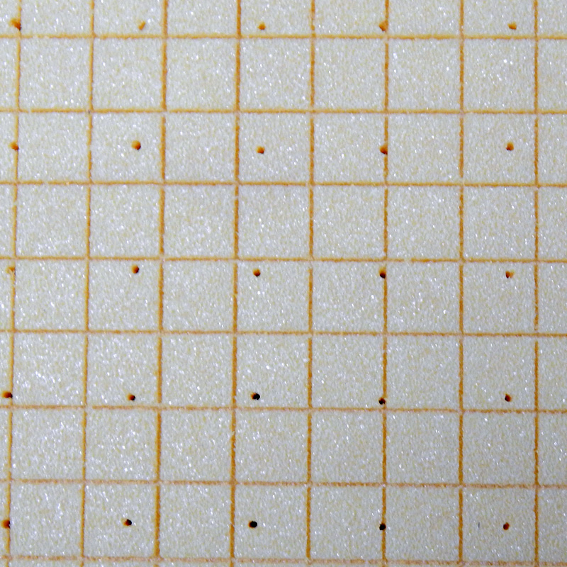
In the first case, all the core has to do is permit resin to pass through at a rate that allows the mold-side skin to infuse at a similar speed to the top skin. Usually core can be purchased with small evenly spaced holes pre-drilled. Foam and balsa cores are available with this option. The holes have to be big enough to let enough resin through but small enough so that they don’t add unacceptable weight to the part. Heavier skin laminates will require more resin and therefore larger holes. This is a case where test panels and controlled resin speed will teach you the right recipe for your laminate stack.
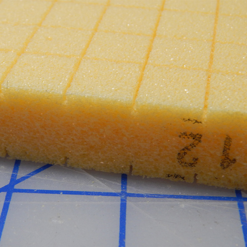
When the core needs to be the “flow medium” as well, it has to have channels to move resin along one or both sides of the surface – as well as permeability to allow resin to pass through. Foam cores can be bought with infusion grooves, which are shallow channels cut out of the foam in a grid. These are accompanied by the same through-holes that allow resin to pass from one side of the core to the other. Sometimes the grooves are only on one side of the core and sometimes they are on both sides. If you choose a core that can act as a flow-media, you can avoid a surface-flow solution across much of your part surface, saving labor – but at the cost of including extra resin weight and cost in your part. Grooved core can increase resin use by 25%.
Some specialized cores like Lantor Soric or Chomarat Rovicore are designed for LRTM or infusion-only and can open up processing options that aren’t available with other types of cores. These are sort of like the “Coremat” of infusion – not perfect structurally, but often the right upside at the right price!
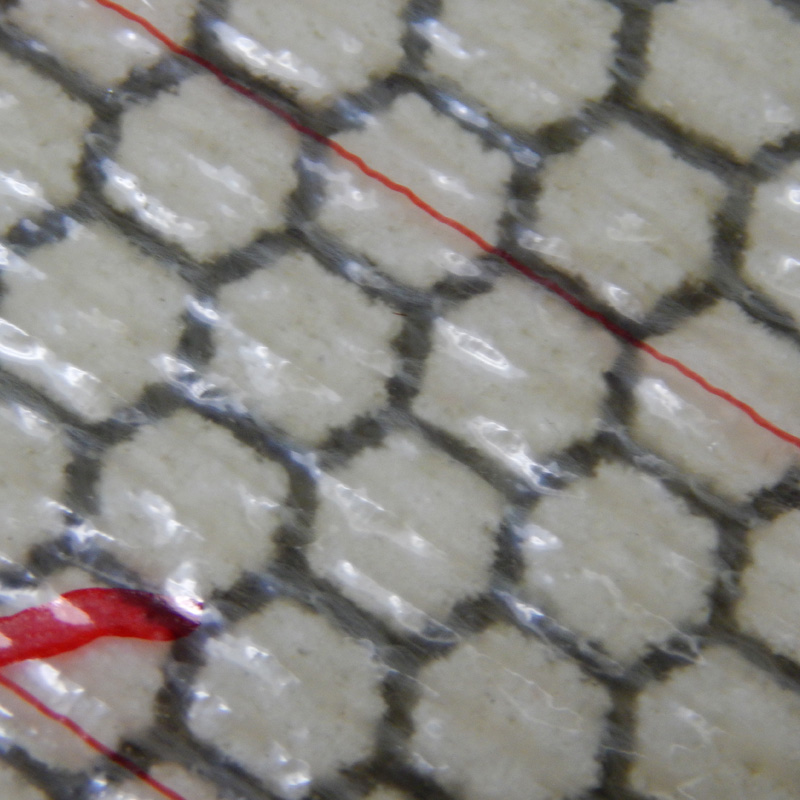
With Soric, the core is a flow-media / structural core hybrid – with microspheres stitched into bundles with honeycomb-like resin flow channels. These types of cores are typically much heavier than foams or balsa because they require so much resin. For variable thickness parts, easy form-ability or rapid production – they are hard to beat. Soric can be combined with foam cores in parts where high-curvature areas would be hard to fit with foam, and too labor intensive or heavy to do with solid laminate.
For more on Soric, check out: Laminate Sample #20: Infused E-Glass / Vinyl-ester with Soric Core
Thin cork core can be a good alternative too, using less resin but offering different types of mechanical properties – and the processing challenges that come with a moisture-absorbing wood-ish material.
Consumables for Infusion
First off, right on top of your final ply of reinforcement, you may choose to use a peel ply. This is a good idea if you are going to do any painting, fairing or secondary bonding on the surface. It is also good general practice and should be seen as a default thing to do. If you use a perforated release film (see below) and do not intend to do any secondary operations besides trimming, you can just use the release film to keep the flow media from sticking to the part. Without peel ply or release film, most flow media will bond to the part and will be pretty much un-removable – except with a grinder. Avoid that – it sucks. Your peel ply choices include plain and coated peel plies – coated ones can release much better and faster but may be less ideal for secondary bonding. There are also teflon coated peel plies that should be used under heavy resin feed features like Enkafusion or large spiral wrap. Once these get soaked up with cured resin they get really hard to remove from a surface. Very un-sticky peel ply helps allow these to “pop” right off – saving much frustration.
[PIC of peel ply options]
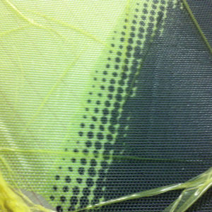
Often it makes sense to use a perforated release film for infusion – especially for thinner laminates where removing the peel ply would be harder if it were all gooped up with a surface flow media. You could also skip the peel ply this way – if you really want to. The perforated release film can make it harder for trapped air to escape into the surface flow media so you have to be careful about infusion speed and good vacuum integrity.
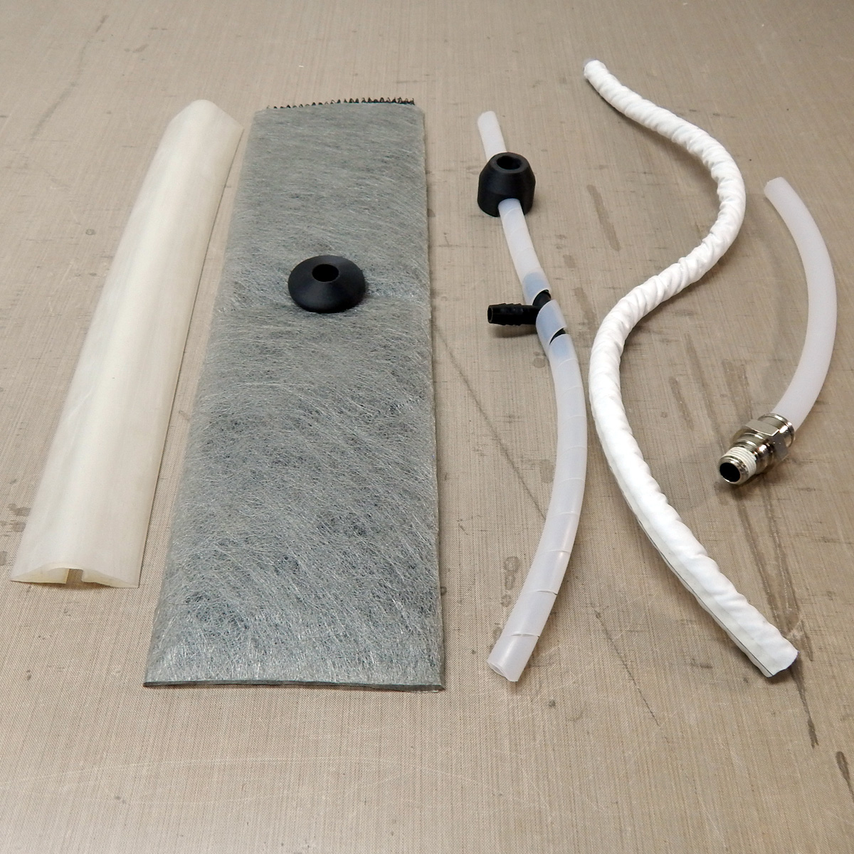
Now you’re ready for resin feed features and surface flow media that works in your application. Surface flow media will be necessary if you are trying to infuse something that is a single skin or that has core without specific flow features. Diamond pattern flow media or “shade cloth” is common. There are many options for resin feed features and vacuum-side manifolds. Spiral wrap is the most common and should be covered with peel-ply so the bag doesn’t get into the gaps and pop. Other products like Enkafusion, MTI (DD Compound) or Dahlvac (Airtech) hose and plastic pipe fittings can make this easier and will be discussed more later. Hoses can be inserted through the bag or through pleats at the edge.
When it comes to choosing a tubing for your feed and vacuum lines there are some kinds that work and others that are trouble. You want something that is clean (no contaminants in the resin!) and that will not break when clamped but also not collapse under vacuum. Polyethylene hose is the most commonly used and in my opinion the best choice.
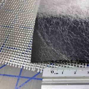
Products are available that can add an inner-laminar flow media between piles of relatively less-permeable material. Often a light scrim can make a big difference in flow rate and wet-out. By adding the flow media inside the laminate and letting it become a part of things you create a situation where the flow front is more vertical – so the bottom and top surfaces infuse at the same time. This can be a big help with thick solid laminates like you’d use in tooling. See picture at left for examples: Chomorat G-Flow with the large open weave and Spunfab thermoplastic veil from Bravolab. Continuous strand mat is also useful as a “leave in place” flow media.
The “plain-vanilla” disposable bag infusion uses the same types of bagging films and sealant tapes as wet layup or low temperature pre-pregs. Standard nylon bag film is great. I strongly suggest avoiding stretchy bag film like Airtech Stretchlon for infusion unless you have a very specific application that makes it necessary. You don’t want your bag to have any elasticity once there is resin under it because it can suck resin up making thicker resin-rich areas under stretched parts of the bag. There is no substitute for a well-fit bag with pleats everywhere you need ‘em.
Vacuum bags can be disposable or re-usable – or you can even use solid “B-side” tools or “contramolds” for a VARTM or Light RTM style of infusion. More on these later on. And that’s just the stuff on the mold… You’re going to have feed lines, clamps, buckets and catch-pots to get resin in and handle vacuum connections.
Kit-Cutting Materials
One of the cool things about infusion is that you don’t have to race curing resin while loading the material into the mold. There is plenty of time to cut reinforcements to patterns and lay things out in a neat and orderly way. Because you may be dealing with complicated shapes and numerous patterned plies, it helps to “kit” these out well beforehand so everything will be ready-made for the actual layup. It’s like how chefs measure out all their ingredients before they start mixing – so they don’t find out halfway through that they are out of eggs!
Cutting kits of materials for production parts is a really good idea. Super thick infusion-specific reinforcements are easier to cut with an electric rotary knife or an automated CNC plotter cutter. You can mark ply orientation in marker on the individual pieces so that layup is faster and easier. Often it is easiest to loft the initial patterns from a 3D model of your part and then make any corrections after manually or CNC cutting the first set. Compound curves and material drape-ability can be hard to model accurately so corrections are often needed to get slip joints and laps to work to plan.
Core can also be cut in kits – either manually or via CNC router. Core ramps and tapers are easy to handle this way and can be standardized after a few initial cut and correct sessions. This can make layup way faster and allow for tight fits between core sheets. Remember – every gap in the core will get filled with resin – and resin is heavy and expensive.
You should also kit-cut any infusion consumables like peel ply, surface flow or spiral wrap – especially if you are working on a tight production schedule.
Make sure to allow for the correction process when planning – better to fuss a little up front than have laminators “custom fit” core or fiber kits over and over – all the while cursing the %#*& engineers. Be open to changes and improvements during production. Things are never fully figured out so baking in a continuous improvement strategy will make your work better, faster and keep the people doing it happier. Avoid cutting like fifty kits of material before the first part is even made – try to keep a minimum buffer of cut kits so any corrections or changes are easy to apply. Layup maps, checklists and numbered plies really help to make layup faster and more accurate. This is one of the huge benefits that infusion offers as a process – it is much more manufacturing-friendly than wet layup for complex or structurally-demanding parts. Application of Quality management processes is way easier actually possible!
When you have a well-sorted set of patterns it may be worth jobbing out the kitting process to a subcontractor or to your material supplier. Several businesses supply marked and cut kits boxed and stacked from your CAD models. This may seem too expensive to you, but it is worth looking into because it might save your team time that more than makes up for the extra money!
Tools You’ll Need
So about that vacuum system. Besides your tooling and leak-avoiding skills, your vacuum system will have a big impact on the success of your infusions. I am of the opinion that for infusion, you have to divide your vacuum needs into two different phases of the job.
The first “high vacuum” phase goes from when you first seal down the bag, through the infusion itself, to right before you clamp off the resin feed-lines. During this time you want as much differential between the air pressure outside and the air pressure inside the bag – so more vacuum is good! Here your big high-vacuum oiled rotary vane pump will be your friend. After a few minutes, flow should be very low, and the pump is working to remove as much of that remaining air from under the bag as possible. This high vacuum will also remove moisture and other volatile materials more effectively from the dry stack.
The second phase goes from when you stop feeding resin to when the part is demolded. Here you want enough vacuum to hold a negative pressure on the outlet – and therefore under the bag. Even if your lines are filled with resin, there is still a pressure differential to be preserved. It just becomes a hydraulic pressure instead of air pressure acting on the now-resin-filled cavity. But you don’t want too much vacuum. The main reason is that you want to keep any volatile material still in the part – water, MEKP, styrene, etc. – from reaching its vapor pressure – and starting to boil and turn from a liquid to a gas. Increased temperature (in general, and from the exothermic reaction of resin curing) and low pressure make it easier for liquids to turn to vapor. And volume-for-volume the same number of molecules of a gas are WAY bigger than the same molecules as a liquid. These huge (ok, visible) “bubbles” can form from a very small quantity of liquid material when it boils. You want to avoid that! Keep that stuff in liquid form by staying below the vapor pressure. Note that temperature is the other player in vapor pressure: higher vacuum or higher temperature will reduce the vapor pressure.
You also don’t want so much pressure differential working to over-bleed your part. Unless you have excellent vacuum breaks or are using semi-permeable vacuum perimeters, it is pretty easy to pull out excessive resin with a strong vacuum. This is an issue with both polyester/vinylester – because of low viscosity – and with epoxy – because of long open time.
So the long and short of it is that for ideal vacuum processing, you want two pumps – one “high vacuum,” the other “low vacuum.” In a pinch, the high vacuum one can be throttled down with a regulator or bleeder valve. It might be better to just shoot the infusion with a lower vacuum pump (25inHg or so) rather than deal with a vacuum regulator and your poor overworked oil-spewing high-vac pump! While I dislike shooting infusions at less than “really good” vacuum, it can be done successfully because there is a pressure differential. You’ll want to feed more slowly so the modest fraction of air left in the dry stack can be effectively chased out by the resin front.
Pump systems made specifically for infusion will often have a regulator so that vacuum can be adjusted. These two phases of the process with different requirements are why. Check out Vacmobiles (NZ) for excellent examples of vacuum systems designed for infusion.
If you are looking for more information on vacuum pumps, check out: Buying a Vacuum Pump

All this about vacuum is making me realize that you’ll need a vacuum gauge. I’m a big fan of digital gauges – and of absolute gauges especially. If you are routinely infusing anything with monetary value exceeding a few thousand dollars there is no reason not to own an absolute gauge. The difference between a “relative gauge” and an “absolute gauge” is that a relative gauge (the normal kind) reads vacuum relative to atmospheric pressure. The absolute gauge reads relative to a complete vacuum. So you could use an absolute gauge as a barometer – but not as a relative gauge! Absolute gauges will give you repeatable readings independent of weather. For important parts, you want to know how good your vacuum is relative to a fixed standard, not compared to today’s weather. And when you’re reading in millibar (1/1000th of an atmosphere) you’ll notice the weather!
Digital gauges are important because they let you get a very accurate read on drop tests. When your digital gauge goes from 10 to 35 mbar , that’s a lot easier to read than having a dial gauge going from “29+” to “29-ish.” In a manufacturing environment, having standards for drop tests and logging the vacuum levels before an infusion is “shot” is important for quality management and potential troubleshooting. Especially when the stakes are high, people will be much more comfortable with metrics that remove judgement.
You’re also going to need some clamps for your hoses and a catch-pot to make sure resin doesn’t get into your vacuum pump. There are endless solutions for clamping a hose, but some are way handier than others! The Vise-grip style pliers that are used for carpet are good. I have some special infusion clamps with a knob that let you adjust the flow – they’re awesome.
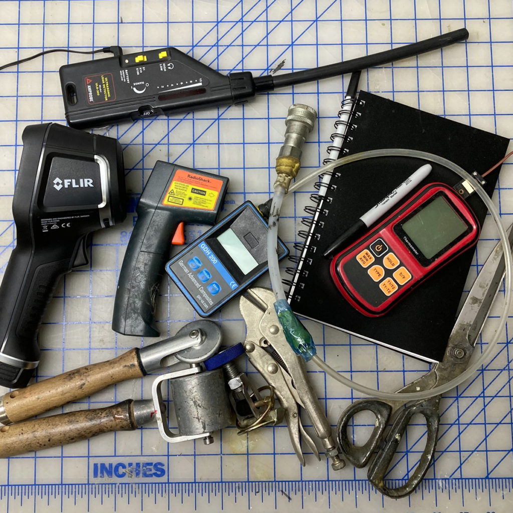
It’s also nice to have some way to monitor the temperature. A point-and-shoot infrared thermometer gun is key – both to monitor part surface temperature and to point into buckets of resin to watch for heat buildup as it starts to gel. For pro-level work a thermal camera is awesome because it gives you a visual heat-map of your world. This is ideal for monitoring a complex infusion because you get so much information just looking at the screen. They’re not cheap though and you don’t want to drop one in a bucket of resin or grab it with a goopy glove.
Finally – because leaks suck – you’ll ideally have a leak detector. You don’t need one – and I only use one if I have a bad drop test and need to go hunting for the problem. They can be a very valuable tool for large infusions when you need to hunt down leaks in a long run of sealant tape or in vacuum or resin plumbing. I understand that a stethoscope works ok, and also that a tube with one end stuck in your ear (gently!) can be good too. Never tried though.
Temperature
Infusion is a game best played warm – or downright hot with epoxy. And controlling the temperature is important. You will not have repeatable success with vacuum infusion unless you can control the temperature of your mold, the dry stack and the resin going in. As you increase the temperature of a mixed resin, it will have a lower viscosity. Typically for every 10 degrees C you raise the temperature, the viscosity will halve. It will also cure faster because thermoset resin gel-times are very heat-dependent. Putting warm resin into a cold mold will not work well – the resin will cool off as soon as it hits the fiber and the stuff in the bucket will go off fast!
I strongly suggest that you avoid infusion below 68F / 20C. It might work but you’re asking for trouble on a lot of fronts. For large things you care about, much warmer is good – like 85F / 30C – especially with epoxy. Adjust your hardener (epoxy) or catalyst for the higher temperature. This is less of a big deal with polyester and vinylester resins because they tend to have lower viscosity.
For fussy things like carbon molds infused with high-temperature epoxy – it can help to be downright uncomfortable with the heat. And make sure everything has had time to come to an equilibrium heat – ideally overnight. Drums or totes of resin warm up slow.
Resin Choices
Your resin choices will usually be determined by engineering and budget requirements. For parts with a gelcoat finish and modest performance requirements, polyester resin is easy and fast to process and inexpensive – and there are many different varieties to choose from. You can get better mechanical properties by switching up to a vinyl-ester resin – with almost no change in processing – but possibly a change in catalyst. Better adhesion properties will allow you to remove chopped strand mat from your layup too. Reusable silicone bags work well with “styrenated” (polyester and vinyl-ester) resins.
For higher performance parts where weight is more critical and gelcoat is less important, epoxy is a great choice. Epoxy comes with some big changes to processing as it is typically higher viscosity and can have a much longer pot life and open time before gelling. You can use in-mold coatings with epoxy but you’ll want to be sure there is good compatibility and adhesion. It’s not as simple as just spraying gelcoat and letting it tack before layup. Epoxy is also not a good choice with re-usable silicone vacuum bags – it eats them!
Unless you are just playing (and even then) select a resin system that is specifically blended and sold for infusion use!
Polyester and Vinyl-ester
There are as many flavors of polyester resin as there are of ice-cream. And when you add in the catalysts (actually “initiators” – but we call them catalysts) there are many more choices! You’ll want to do some research and ask your resin suppliers about the varieties of resins they supply and the recommended catalysts. I’m going to do a quick run down from cheapest to most expensive:
- Orthophthalic Polyester (Ortho) resin is generally the least expensive – also called “general purpose” by many vendors. You want it to be specifically made for infusion or RTM – with a low viscosity. It will shrink more than other options and does not have good resistance to chemical or moisture intrusion. It seems to be hard to find unblended “ortho poly” infusion resin – but I haven’t tried hard. Maybe it isn’t a good option…
- Isophthalic Polyester (Iso) resins offer better chemical/corrosion and moisture resistance. They are generally tougher and stronger in cured form than ortho or DCPD-blended polyesters.
- Vinyl-ester (VE) resins are like a hybrid of polyester and epoxy (kinda) and offer mechanical properties significantly better than any of the polyester resins. Improved toughness and strength as well as better resistance to water and corrosion come at a cost though – vinyl-esters can cost 2-3 times as much as general purpose polyesters. They also shrink a lot and can be more fussy to deal with.
- DCPD + Ortho / Iso / VE Blends are polyester or vinyl ester blended with dicyclopentadiene. DCPD can be its own resin base, but most often you’ll see it blended for hybrid performance characteristics. The DCPD helps with reduced shrinkage and reduced styrene content. This is helpful from both a cosmetic (low shrink) and worker safety (lower styrene) perspective.
Half the battle with polyester and VE resins comes down to the catalyst choice and catalyst ratio. First a bit about the different catalyst (“initiator!”) options:
- MEKP (methyl ethyl ketone peroxide) is the most common of the catalysts. It comes in a bunch of different types – with three active components (hydrogen peroxide, monomeric MEKP, and dimeric MEKP) mixed in different relative quantities, it can give a broad range of curing outcomes. The hydrogen peroxide level controls the gel-time and the monomeric and dimeric MEKP control the cure rate and cured hardness – and the exothermic heat. Low-peroxide MEKP blends can help reduce foaming and extend the gel-time of infusion systems without impacting the cure laminate properties.
- AAP (Acetyl Acetone Peroxide – also: 2,4-Pentanedione Peroxide) is the fastest of the catalysts. It allows fast cycle time and is good for thin laminates where the increased exotherm isn’t going to be a problem. Probably not the best choice for infusion.
- CHP (Cumyl Hydroperoxide) offers a more gentle cure with lower “exotherm” temperatures. This is helpful with very thick laminates that might otherwise crack or warp from excess heat. It also helps with cures performed at elevated temperatures. One additional factor with vacuum infusion is that CHP “boils” at a significantly higher temperature/vacuum level than MEKP and is less prone to forming bubbles in the laminate if conditions are ripe for phase-change.
Each of these is often blended with others to create a catalyst with a mix of properties. An AAP/CHP blend can have fast cure times with less out-of -hand exotherm and is suitable for thicker parts in a fast-cycle time situation. MEKP/CHP blends are often used as a “summer blend” for open molding because the CHP slows things down and keeps the resin from curing as aggressively – without risking under-catalyzation and poor cured resin properties. MEKP/CHP blends like MCP-75 (75% MEKP, 25% CHP) can reduce exotherm and slow gel time, while still building adequate cured hardness. It is better to slow things down with a blended catalyst than to risk under-catalyzing with straight MEKP – always try to stay above 1.25%.
For infusion, a standard MEKP, lower hydrogen peroxide MEKP, or MEKP/CHP blend will be a good place to start. Unless you are doing something special (RTM, fast cycle time, etc.) AAP will probably not be the thing. Straight CHP can be an option if you are dealing with heated molds or thick laminates – it has the added benefit of a higher vapor pressure.
Catalyst choice is complicated and for each resin system, there are combinations that work well and ones that don’t. Compared to open molding, infusion has more strict requirements and adequate (but not too long) gel time is really important! Your resin manufacturer should be able to point you in the right direction for a place to start.
Epoxy
Epoxy is less fussy than polyester because you typically just mix part A and B and you get what the manufacturer wants you to get. Choosing the resin system and exactly what part B to put with your part A – that’s where the fun is!
Most epoxy infusion resin systems come with a variety of hardener speeds and can be tuned to give the right open time for the specific job. Data sheets from manufacturers will tell you pot life, viscosity and cure time for each combination of hardener and resin. Viscosity vs. gel time will be your biggest concern with infusion epoxy. I like to plan for parts to be filled in 1/2 the gel time of the resin m- just to provide a margin of safety if things go off the rails feed-wise.
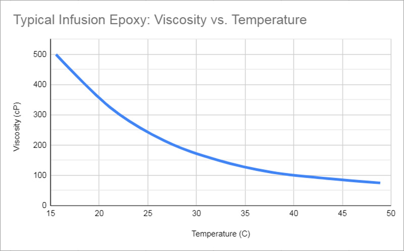
Keep in mind that you can adjust the temperature of the resin and the loaded tool you’re infusing – this will help you further tune your resin choice. As you increase temperature, the viscosity will drop like crazy – so I suggest using epoxy warm – even hot – if you are trying to get the best infusion performance you can.
Epoxies tend to have higher viscosities than polyester or vinyl-ester infusion systems. This is because they can – with longer open times and more control over cure parameters. Epoxy chemistry also loses some desirable performance characteristics when thinned too much, so manufacturers tend to suggest adjusting the hardener speed and the temperature of the infusion to make up for higher mixed resin viscosity. There are exceptions though, so if you are using a lower viscosity epoxy, you may be fine in just a warm factory.
Test Panels: Make Them!
I’m not saying you have to make test panels – but you should make test panels! Those are your chips (or your boss’s, customer’s, etc.) you’re playing with. Screw-ups and horror stories are common when it comes to infusion and materials and labor are expensive. Don’t make another sad story – make test panels!
Good test panels tell you what you need to know by sampling the actual methods you will use for larger parts. Ideally they should be made by the same team with the same equipment (vacuum system, consumables, tooling material) to remove as many variables as possible. You’ll be able to confirm gel times, and distances traveled by resin at different temperatures. For large parts with multiple or staggered feed lines, you’ll need to know how far apart to place them – and test panels will tell you. Don’t be afraid to make larger test panels than you think you should – sometimes this can be the difference between finding and sorting out a process issue and… a big problem. If waste is an issue, you can plan to infuse some smaller parts before larger ones to make sure things work well in lower-stakes situations.
Laminating
Before you laminate on a new production tool, make sure you have vacuum tested it to get a baseline. This usually means covering the surface with a breather fabric and bag and then pulling a vacuum – and then chasing down any leaks until it’s really good. You want to have a base-line for the mold but just as importantly for your vacuum system. Often you’ll find the mold is good but there are leaks in the plumbing and these – while they probably won’t mess up your infusion – will drive you crazy. Do this before you release coat your tooling, so if you find areas that need repair, it will be easier.
Release System
So now you have a vacuum-tight mold all ready to lay-up. You’re going to need to apply a release system to keep the part from gluing itself to the tool!
If you are planning to use wax or PVA, I suggest you look into other options. There’s nothing terribly wrong with these but there are better choices. Lots of suppliers make semi-permanent chemical release agents that give good surface finishes and are less prone to application error or contamination. Talk to your material suppliers and get samples and do tests.
Remember mold primers and sealers can make a big difference – they don’t call them “release SYSTEMS” for nothing!
More about release options here: Guide to Mold Release Systems
Gelcoats and In-mold Primers
The release system has been applied and allowed to cure/dry/whatever it needs. If you are using a gelcoat or in-mold primer now is your time.
For polyester and vinyl-ester parts, gelcoat application is done as you would for an open molded part. Mask and spray. Keeping overspray off the areas where the sealant tape will go is important. For production parts it is common to laminate a “spray mask” which is just a thin skinned part that covers the areas of the mld where you don’t want gelcoat.
There are some epoxy-compatible gelcoats that have a proven track record (for example: Polynt IMEDGE ECT120, RESOLCOAT 9040 PX, Crystic GC 253PA, Easy Composites GC-50.) Most are applied in similar fashion to standard gelcoats – but you should plan to do some research and testing.
With epoxy laminates, in-mold primers are common. They save some work in prepping and finishing the part surface and can often have some type of “primary bond” with the laminating epoxy if the process is timed right. Lots of options – again – be sure to test first!
Skincoats, Surface Films and Print Blockers
The gelcoat or primer has been sprayed in and allowed to cure to the extent that it won’t come off when you touch it…
With polyesters and vinyl-ester resins, the issue of shrinkage is real – and it can cause nasty cosmetic problems unless you address it. One common solution is a pre-laminated skin coat. This can be as much as 3oz (90mils) (800-1000gsm) of chopped strand mat applied over the gelcoat very carefully. For larger parts, a chopper gun is ideal because it means no binder in the mat and no overlaps – so laminating is easier. Skincoats should be done without any bubbles or voids – and as few laps as possible. Voids will show in the gelcoat surface and require repair and thick areas will shrink and print into the gelcoat surface. This can be done all-over a part or selectively in areas prone to cosmetic issues – like areas with heavier reinforcements or core tapers. Skincoats should be done with a compatible laminating resin (no wax!) that will remain open to bonding chemically with the resin you will be infusing to make the part. Be careful with DCPD bends – they can have a much-reduced “open window” for secondary bonding. Make sure the skincoat is cured to the touch (like gelcoat) before applying additional laminate.
Even though epoxy shrinks much less than styrenated resins, it is sometimes good to use a skincoat and standard gelcoat if you need good cosmetics out of the mold combined with an epoxy laminate. This skincoat can be thinner than the heavy one required with polyester or VE – but it has to be thick enough that it will cure fully and that you can mechanically prepare it for bonding. I am assuming a styrenated skincoat resin here – you can use epoxy but because it only generates cured hardness with temperature, it won’t help you much with isolating print. Avoid woven skincoats – they are too thin and will be a headache to bond with the primary laminate – and they like to peel off. With epoxy, you aren’t relying on chemical bonding, instead the epoxy has to mechanically bond to the cured skincoat. This is an area where testing is critical. Assume nothing!
Sometimes your part will need a surface ply that is co-infused with the laminate to help with cosmetic issues. This could be a thin spun polyester veil or a mat like Lantor Finishmat or a fluffier non-woven that retains a resin-rich layer against the part surface. Even a light woven can help because the fiber bundles are smaller and the pockets of resin between them will shrink less – but a non-woven is better. Glass cloths have the nasty habit of playing peel ply and peeling off in big strips at edges and in damage situations. This can be an issue with carbon – but less so. Cloths do have the benefit of being more damage tolerant than unidirectional or stitched non-crimp reinforcements.
With epoxy, these co-infused printblockers work best if you post-cure the part – ideally in the mold and under vacuum. Again, talk with your suppliers and learn what other manufacturers use.
I’ll try to beef up this section but different things are available in different parts of the world and the technology is always improving. Getting good cosmetics/”surface profile” is hard!
Slip Joints and Laps
When you start laying material into your mold you’re going to have to decide what to do everywhere there is a step or corner in your part. Also reinforcements come in a fixed roll width and you’ll have to lap them to get anything wider. Here you need a plan!
Check out this article: Slip Joints and Why You Need Them!
Slip joints are what you do inside corners to allow the fiber to fully fit into the corner without bridging – or trying to stretch across. If fiber bridges you can get voids and resin-rich areas in the outside corners of the part. So what you do is cut the fiber into the corner (at, above, or below) and then lap the neighboring piece over by a certain amount. This makes a full-strength joint that also allows the fiber plies to slide by each other under pressure and fully conform to the mold surface. The amount you overlap is dependent on the fabric type and weight.
You want to be as consistent as possible with the lap widths, either at the edge of a ply or in a slip-joint. For a 12oz / 400g e-glass biaxial, you might lap 25-30mm / 1-1.2in. Unidirectional plies only need to lap if they are transferring load – if they run along beside each other you’d just be doubling a set of already parallel fibers.
In a production environment, each lap and slip joint should be specified, and they should be staggered so they don’t stack up. It is easy to over-fill a corner and create an inside wrinkle. Slip-joints can also mess with core-fitting – so they need to be considered when shaping core kits. If you want something done a certain way, you have to be very clear about how to do it – in a way that can’t be ignored or forgotten about!
When laying up heavy dry reinforcements, a roller can help press fiber into outside corners and “break in” your slip joints. Many laminators find that the smooth handle of scissors work well too. Be careful on gelcoated or pre-laminated parts not to crack or pre-release the surface layers. Rollers are more gentle!
Spray Adhesive
As you stick plies of dry reinforcement (and core) into the mold, it will be necessary to hold them there somehow. Unless you’re making a flat panel, gravity will mess them up and you’ll have real trouble keeping things together. This is where spray adhesive (spray tack, spray snot, etc.) comes in!
By using a very light spray of contact adhesive, you can glue the plies together so they don’t move around. Notice I said “very light!” Too much will interfere with the resin and leave nasty bubbles and smeary surface contamination on your parts. It is best to use a product with a quality-control tint in a production situation so that you can see how much has been applied. It is all too easy to get frustrated and hose the place down with adhesive only to have real problems later on.
For large parts, adhesive can be got in canisters with long hoses. This is both faster to apply and less expensive and wasteful than aerosol cans. Canisters can be refilled. There are many brands of adhesive use for stacking dry materials. Some are resin soluble, others are carried out on the resin front, and other just hang out forever in your part.
[See the end of the article of a list of spray adhesive products. Appendix C?]
There are also fiberglass tapes that can be used to hold plies together but I haven’t used them.
First Skin
So with all those details, you get the first skin laminated in the mold – nice laps and slip joints, not much spray adhesive – and extra reinforcements where your plan calls for them. It is good to balance extra reinforcements and tapered out single skin zones across both sides of the core – but that’s more of an engineering thing than a layup thing. So it all looks good and you’re ready to fit that core now! If you don’t have core and layup is complete, skip down a page or two to the “Flow Media and Bag Stack” section.
Core
Cored parts have the added complexity of being almost two infusions in one. The top skin and the mold-side skin both need to be filled and the core needs to allow resin to reach both sides.
For solid foam or balsa cores, the fit has to be quite good or the joints become big tubes full of flowing resin. This can throw off your plan by redirecting resin in the wrong direction – or in the right direction but too quickly. This is called “race-tracking” – when resin finds an easy way to get ahead of where it should be! It can cause concern at best and big dry spots – “islands” – at the worst. It is totally fine to wedge strips of foam into areas where the core fits poorly – better to have sloppy foam in there than a huge river of brittle heavy cured resin. This is an area where kitted core made on a CNC can pay off in a big way for production components!
When using surface flow media the biggest issue is getting enough resin through to the bottom skin. Holes in the core let this happen and it works fine as long as they are big enough and the resin flow is slow enough to allow any trapped air or vapor to escape. The flow front ends up being staggered with the mold-side skin lagging back – sometimes by a lot. It becomes very important to hold back any surface flow media from core ramps so the resin in the top skin doesn’t get to the area where the skins touch first, choking off the escape route for the air in the bottom skin.
For an example, check out: Laminate Sample #9: Epoxy Infused E-Glass With Balsa Core
When using the foam itself as the flow media, it is important that the grid-scored in the foam is sized right to allow resin to fill the whole laminate before moving on. Sometimes when you demold a cored part with grid-score foam, you can see air trapped in the middle of each square formed by the scoring. If this happens you should slow the feed down or choose foam with tighter grids.
In some cases you can get foam that is only scored on one side or in one direction. This lets you control the flow more completely but not without risk of having one side out-run the other.
Foam Core Details
Core ramps are as important with infusion as with any other type of layup. Places where core thickness changes or drops out all-together should be tapered at a 2:1 (at a minimum) ramp. Tighter 1:1 ramps work, but not as well either structurally or in terms of manufacturability. If your part has been engineered, the dimensions of core ramp details should be specified.
The density of the core doesn’t impact the process much with infusion – as long as it fits well and has the right sized holes in it you could use pretty much anything. Higher density cores have smaller cells and take up slightly less resin. High density inserts made from Penske / Coosa board, G10, solid glass, carbon plate or metal all work fine as long as they have the requisite resin flow features and fit tightly with the rest of the core kit. It is a good idea to put a layer of fiber between inserts and core if there are rebated inserts – this will help resin uniformly fill the joint.
Balsa and cork cores can be problematic because they aren’t closed-cell – and they hold air and moisture. Even if you “soak” (hold for a long time) your dry stack under vacuum for hours, you may find that after your infusion is cured there are small bubbles and voids from gasses that took a long time to escape from the wood. The best thing to do is maintain your wood cores at a low moisture level in storage and leave the dry stack under the bag (and ideally warm – to reduce the vapor pressure) for as long as you can – overnight is great.
Cut our sliced foam and balsa cores allow you to easily build curved parts without complicated core fitting. There are a variety of cut and slit types: single cut, double cut, even triple cut – as well as contour scrim style. Be aware that the core cuts jam closed on the inside of curves and open on the outside. This has a dramatic effect on the flow speed as the resin will flow very well through the open contours and not-at-all through the closed ones. Often a surface flow media will be a good match with contour-cut foam. Make sure you test that the knife-cuts will allow resin from one skin to the other – but better to have core that has perforations as well as knife cuts.
One weight-saving option for foam cores to avoid the heavy resin in the core-kerfs is to thermoform the core to fit. This is a ton of work and is usually only a good option with pre-pregs where the cook itself gives the core the flexibility to really conform. With thin low-ish density core it can work well for infusion too. Make sure you drill the perforations through the core after the thermoforming so they don’t get choked off as the foam bends. There are core kitting vendors who will thermoform core to drawings – check out Curveworks.
Core on a Roll
Sometimes you’ll need to add some thickness, save some weight – but not too much – and also need a flow media for your infusion. This might be a case for Lantor Soric – or maybe thin cork! Soric is only a few millimeters thick – less than ⅛” – made of bundles of microspheres sandwiched between non-woven surface plies. It uses a lot of resin compared to foam, but handles all the resin distribution for both skins. There are a bunch of styles and thicknesses available.
This kind of infusion core can be used alongside foams and balsa for areas where conform-ability is an issue but 3-5mm of single skin laminate would be too heavy. You should lap it up adjacent foam core ramps if possible rather than butting the Soric to the base of the tapered foam.
Second Skin
For cored parts, you’ll have the second skin to lay up after fitting the core. This should be just like the first, except now you have any core features to deal with too. I think you should consider slip-joints at larger core ramps – but that’s just me!
It is sometimes (but rarely) preferable for larger complicated parts to break up the infusion by separating the inner and outer skin infusions and bond bonding core using filled resin and vacuum bagging. This is really only good for large complex things where weight and core-bonding are an issue and it is nice to be able to detail the core before laying up the top skin. You use up lots of time and waste about 3X as much consumable materials.
Flow Media and Bag Stack
You may not need flow media but you’ll definitely want a vacuum bag! If you do choose to use a surface flow media (and even if you don’t) you’ll probably want to use a peel ply. Plain uncoated peel ply works ok but it’s harder to remove. Coated peel ply is easier – but it costs more. Decisions!
One very important thing for all the process material that goes on is that you remember slip joints! Just like the fiber, it can’t be relied on to stretch. Even if it does stretch, as soon as the resin is infused and the part is facing a lower pressure differential, these stretchy areas spring back causing voids and big exothermy resin-rich areas. Always slip joints! Slip-joints forever!
Peel Ply
At a bare minimum you should put peel ply in any place you plan to do secondary bonding. I like to put it everywhere because the resulting part will be tidy and it won’t have sharp resin ridges from wrinkles in the bag.
Plain nylon peel ply – the “red stripe” kind is a good place to start. It is easy to conform to surfaces and to control – and spray adhesive works better – and its cheap. The coated peel plies tend to be less drapeable and don’t want to stay in place. Cutting strips of peel ply on the bias, +/-45 to the roll orientation, makes for very conformable strips that can be slip-jointed easily and don’t cause big wrinkles over complex features.
It is sometimes nice to double-peel-ply areas where you’d like to remove the outer layer but still leave a layer in place to protect areas you plan to bond later. I’m a big fan of leaving peel ply on parts until you’re ready to do something with the surface! The problem with infusion is that the surface usually has flow-mesh stuck to it and nasty resin ridges from the bag.
If you are using spiral wrap or Enkafusion on the surface of your part, I really like porous Teflon peel ply to help release that from the part surface. It can be very hard to chip cured feed-lines off your part without damaging it. The Teflon peel ply isn’t cheap but strips of it under feed features work great!
And if you’re using a combined peel ply and flow media like Compoflex RF3, you don’t need peel ply over all of you part surface, just the area beyond the extents of the surface flow.
Peel-ply is also the go-to for covering up spiral wrap. It is good to cover it because it keeps the bag from getting sucked in around corners and potentially either popping the bag or choking off the spiral-wrap tube. I like to apply the peel-ply around the spiral wrap before putting it on the part – laying the spiral wrap 1/4 of the way across of a strip and folding it over with spray adhesive. For bigger parts you can buy pre-made spiral wrap with a cover or make your own out of perforated tube, wire spring, or similar tubular base covered with stitched peel ply, flow mesh, or Compoflex.
Perforated Release Film in Infusion?
Sounds a little strange to use a perforated release film, but yes! For parts where there are thin skins or you will need to leave the part in the mold without pre-releasing it it can be a good idea to use a layer of perforated release film between the peel ply and the flow media. This increases the angle of the “flow wedge” we’ll discuss below but it can help with removal of the flow media and also limit the resin flow to a very systematic pattern. Depending on the perforations (size and hole density) you get a very well-metered resin supply to the laminate and it can help give air time to escape. It is less of a good idea with thick laminates because they need slower feed and have more potential air and vapor to allow room to escape.
Surface vs Inter-laminar Flow
If you were going to use inter-laminar flow media, we’ve missed the boat. That needed to happen back in the layup phase! But that’s probably ok – unless you’re using core (grooved foam or Soric) you’re probably best off with surface flow media – if you need any at all. There are some interesting products that help add infusion-friendly flow channels inside an otherwise very dense laminate stack but that is beyond the “intro” scope here.
Now infusion works just fine without any flow media at all – it just takes forever! The issue is permeability through the compacted fiber stack. Think about how hard it must be for the resin to squeeze in and around each fiber – it really takes a lot of energy to do. Now imagine cruising through the perfectly regular ins and outs of a nice flow mesh – it’s a breeze! The reason to use surface slow media is that it lets the resin flow further and reduces the number of feed lines needed. The resin doesn’t have to fight its way sideways through inches (25 millimeters-s) of compact fiber – it just has to work its way down from the top to the mold surface.
[Vertical Flow Front vs Wedge Flow Front]
In an infusion without flow media, the resin travels through the dry stack pretty much in a vertical front – no further ahead against the mold or on the bag-surface. With surface flow media, it travels like a wedge – ahead on top, lagging behind on the bottom. The geometry of this wedge depends on the laminate. This is much less ideal from a trapped air perspective because air can’t come up to the surface to escape through the peel ply – it has to travel through that super-compacted laminate.
The big benefit of flow media is speed and the need for far fewer feed lines. You might only get resin to feed 6” / 150mm through a solid laminate before friction got the best of it – so you’d need feed lines less than 6”/150mm apart. With surface flow you can get 24” / 600mm of flow or more between feed lines. So flow media on the surface is a compromise – you get an easier feed layout and much less wasted tubing, but you have to deal with a wedge-shaped flow front and all that implies!
Flow Media Orientation
Most surface flow media is directional. The (usually red or green) plastic flow-mesh flows about twice as fast in the roll-direction as across it. Most shade-cloth is more uniform but holds much more resin. Compoflex seems to be directional – like the mesh.
If you’re using a material that flows resin directionally this can be used to optimize the feed rate. If you don’t attend to it, the variability of putting it any-which-way can cause problems!
Flow Breaks and Resin Breaks
If you have a surface flow media, it will distribute your resin across the part – but it can also cause lots of problems because of the wedge-shaped flow front it creates. The biggest is the problem of inconsistent part filling and the risk of leaving “islands” or dry spots that get blocked off from the vacuum side by resin. Two key features of flow media and peel ply layout will help you avoid problems. Here’s a picture:
[image of flow and resin breaks]
The first is what I’ll call a “flow break” – also called a “dead zone” or just “leaving the flow media back from the edge of the part a bit.” The goal here is to make it easy for resin to fill most of the part, but leave some perimeter without any flow media. This puts the brakes on resin flow and breaks the link of easy-to-flow path from the flow media to the vacuum side manifold. Doing this forces the whole part to fill and then to slowly fill the remaining perimeter after the slower-filling areas with surface flow have caught up.
The second feature is called a “resin break.” This is just a low-permeability perimeter around the edge of the part that keeps resin from flowing in large volumes into the vacuum side manifold. This is a secondary version of the flow break that lets air escape the part edge without also allowing a meaningful quantity of resin to fill and choke off the vacuum side plumbing.
Typically the resin break is made with a single layer (or maybe two) of peel ply. Peel ply is a very light weight woven fabric so it lets air flow through but really limits the volume of resin – resin being so much higher viscosity than air! These two features should also be used with core-based flow strategies. You just need to make a low-flow isolation between the edge of the core and the vacuum manifold(s).
Vacuum Manifold
Typically the vacuum manifold or perimeter will be at the edge of the part, outside the resin break and right up near the sealant tape. This is the “goal” for all the air in the part – and maybe some of the resin too.
The ideal situation is to have the vacuum manifold near the highest edge or around a higher perimeter of the part, so the air will work its way up and out. Air will want to float on resin so why fight it… unless your part geometry makes you.
For large parts it is a good idea to break up the perimeter so that if resin reaches one area faster it doesn’t choke off the vacuum for the rest of the part. This is called “segmenting” the vacuum perimeter – segments can be just a few feet/meters or much more. The complexity of your perimeter will drive the number of segments needed – more complicated parts probably need more segments. Leaving gap of 6″/150mm in the perimeter spiral wrap and plumbing each separate section to your catch pot(s) will allow you to clamp off the ones that fill first, leaving the slower areas still connected to vacuum.
Feed Line Setup
If leaks are the biggest issue faced in infusion, feed layout and flow breaks and resin breaks are the second biggest problem area. Feed line spacing and fill order is sometimes hard to predict – especially with large and complex parts. This is where experience can make a big difference – it gives you a sense of how things will work almost from the resin’s perspective. The problem with experience is that it can make you comfortable when you should be cautious and concerned! The best thing to do (as always) is make test panels with your exact laminate stack and feed system, with the proposed feed-line spacing, at the right temperature and see how it works.
The process of vacuum infusion gives you an incentive to do the biggest layup possible with as much in there as you can: skins, core, sometimes reinforcing structure too. This means it becomes more worth-it to test. Cheap mistakes are way way better than expensive ones!
Resin Feed Rate, Flow Rate, Stack Permeability, Resin Cure Speed, etc.
It is really important to estimate how much resin your part is going to need. Your whole infusion depends on being able to deliver the right amount of resin into your part in the time you have before the curing reaction starts. The best way to do this is by having done it already! This is where test panels will be a huge benefit if you are infusing anything large or complicated.
You can get pretty good estimates by considering your target resin to fiber ratios and then backing out the amount of resin you’ll need from that. This works ok with all-fiber layups, but with core there is the huge variable of resin up-take in the core itself, and the resin needed to bond the core, and the resin used to fill up the bleed holes or feed grooves. This can be a lot of resin.
The feed lines, flow media and the rest of the consumables takes up a good bit of resin too. With test panels this can be measured too. You can develop a rule of thumb for how much resin the flow-media takes up. Peel ply will use some too – but not much. The volume in the hoses is easy enough to calculate – they’re just long skinny bendy cylinders.
So you have an estimate of how much resin you need to feed. This is a good starting point for coming up with your feed line layout and determining what diameter feed lines to use. Flow rate depends on many things:
- Mixed viscosity of the resin
- Effect of mold temperature on the resin viscosity
- Diameter of the feed lines
- Length of the feed lines
- Obstructions like barbed fittings, t-connectors, etc.
And there are other constraints to deal with too:
- Gel time of the resin at mold-temperature
- Permeability of the laminate stack
- Flow media
So there’s plenty to consider!
Pressure Drop-off and Fluid Friction
As resin flows through a part, it slows down the further it gets from the feed line. This makes sense because any additional resin to reach the flow front has to work its way through the laminate or the flow media and this takes energy. Friction is a real concern, both between the resin and the fibers and flow media that make for a real maze to flow through – and internal to the resin fluid itself. The further you flow, the more friction will slow things down. This is why flow media helps so much to spread feed lines out – it is a much lower-friction route to resin distribution than through the laminate itself.
The pressure differential between the atmosphere pressing on the resin in the feed bucket and the vacuum under the bag is greatest at the point where the resin first enters the bag. From then on, it is countered by the friction of moving the resin along and the fact that the resin actually starts to equalize the pressure differential as it fills the part. As a part fills, the compressed laminate is no-longer pushing up on the bag as the atmospheric pressure pushes down. Now the resin is pushing up – but lower pressure is coming from the connection to the vacuum pump. Now it is transmitted hydraulically through the resin in the part and the vacuum perimeter.
The resulting pressure gradient across the infused part makes for slower and slower flow-front speed as a part fills. Out of the gate there is the full pressure differential of the vacuum – this drops off and by the time a part is almost fully infused, the pressure differential only exists at the flow front, not across the entire remainder of the already-infused part. This can lead to problems with over-filling and varying part thickness – and therefore fiber volume fraction.
[PICTURE! – wicked confusing]
So the more a part fills, the less pressure there is to make it fill more. This is why feed lines have to be pretty close together. Even if you had a resin that didn’t gel for hours and hours, there is still a limit to how far it will go under a bag. You can tweak this with changes in all the parameters: resin viscosity, laminate permeability, and resin volume, but it is a reality.
Resin Flow Rate
You need to be sure that your part will get enough resin delivered to the feed features to fill in the given time. Feed line diameter can be a limiting factor, especially for large parts. Poiseuille’s law allows you to calculate the flow rate of a viscous fluid through a tube given a pressure differential. Longer hoses will have reduced flow rate, as will smaller diameter hoses. You want more hose capacity than you absolutely need!
[Poiseuille’s Law Calc Example]
Resin viscosity matters here too. The same part will require larger hoses (or more of them) with higher viscosity epoxy than with low viscosity vinyl ester resin.
Typical Feed-Feature Layouts
The point of a feed layout is to get the resin to all the areas you need it without trapping any “islands” of dry laminate in the middle. Because of laminate permeability and resin viscosity, there is a limit to the distance you can feed. We’ll pick a distance that resin can reasonably flow (with the air of any surface flow media) and call this the “flow distance.”
For large parts, it is necessary to break the surface up into zones and set up the resin feed lines to get resin to the whole part. Feed lines can be fed in a staggered fashion, where each zone is filled and then the next zone is filled – like dominoes knocking each other over. The distance between lines should be a bit less than the flow distance. If you need to fill your part faster, put the feeds closer together.
[pic: staggered vs tree type of feed layout]
[PIC: branched feed lines]
The other common approach is to break up the feed features into main lines and branches – like a tree. The main line(s) brings resin into the part, and secondary feed features are branched off leaving no area wider than the flow-distance of the resin. When possible, this is preferable because the resin flow starts once and you don’t have to worry about timing the opening of subsequent feeds. If you open a sequential feed-line too early, you can trap air – too late and you waste time. Opening too late is better – just remember to bleed out the air in the feed line as the resin front passes.
If you have the option to feed from an edge of the part, this can be very nice and handy. Also feeding from the middle of a panel out to both edges is a quick way to handle larger spans. Either of these can be set up in a “half-a-tree” format, where the main feed – or “trunk” – line has branches off one or both sides.
The balance you need to strike is avoiding islands while having resin fill the part as approximately the same time everywhere. Your flow break and resin breaks can play a big part in equalizing the fill time when some areas fill faster and some lag behind.
Feed Line Features and Options
Your feed line grid will have to be appropriate for the type of feed feature you choose. And you have options!
The simplest is spiral wrap covered in peel ply. This is a cheap disposable resin transfer and release mechanism – a hose with a spiral slit for the resin to get out. You have to cover it with peel ply or the bag will poke through the slit and either block the tube or pop – maybe not always but it’s worth avoiding! Spiral wrap can be placed in a pleat in the bag for small parts and then slid down to make contact with the part surface once resin is flowing and then pulled up again before the resin gels to avoid leaving a print in the part surface.
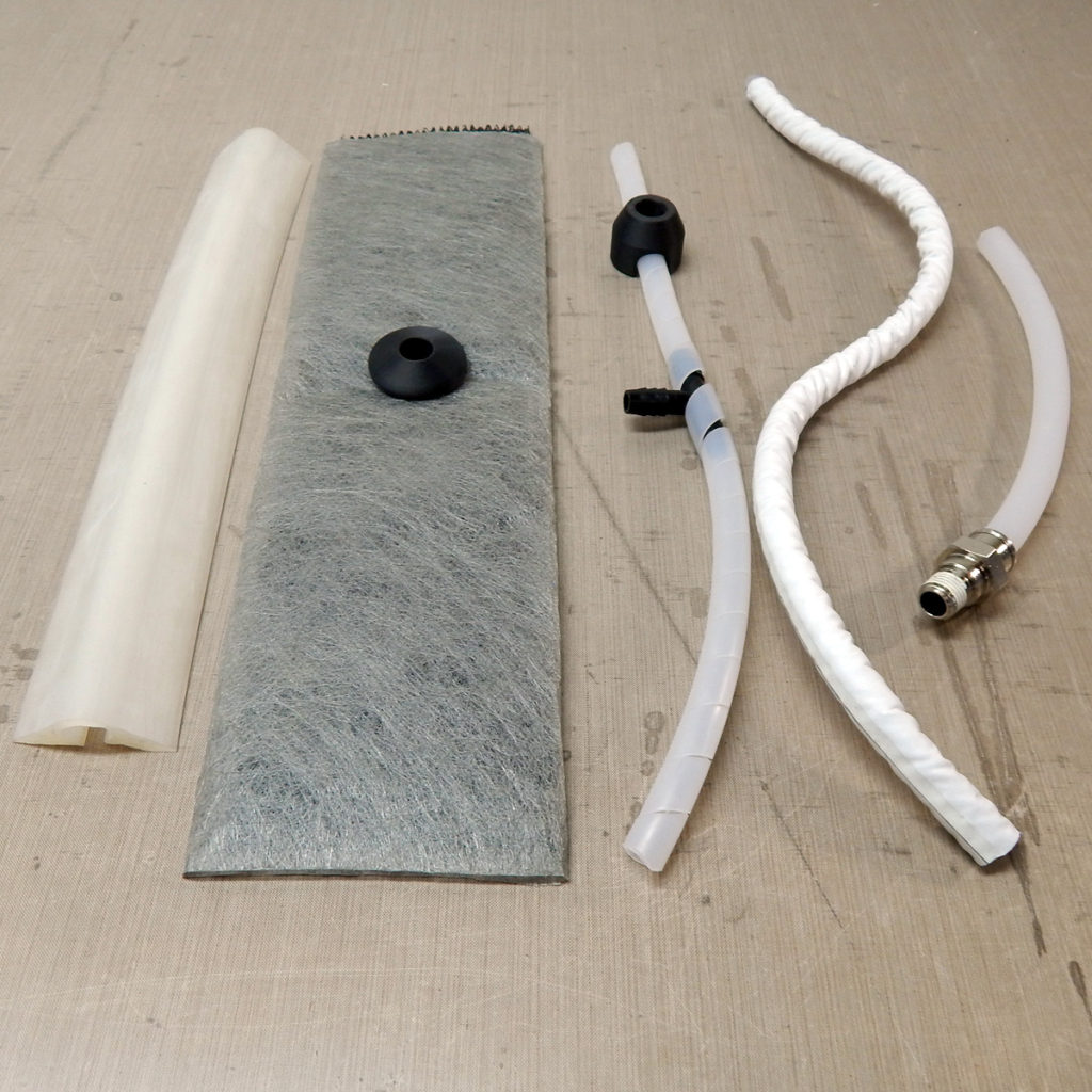
Spiral wrap can be spliced with polyethylene tube or polyethylene barbed fittings – linear splices or T-fittings. To connect resin feed lines, the spiral wrap can be put over the end of the feed line which is then run through a pleat in the bag. Alternatively a plastic fittings can be placed over the spiral wrap and then a feed line can be punched through the bag (sealed with sealant tape) and into the connector.
Another good option is a product called Enkafusion (Airtech Flowstrip is a similar product) that is a flat permeable tube filled with a strip of flow media. This sits on top of the part – ideally over a coated or teflon peel ply – and allows resin to flow along the strip and also penetrate down into the laminate. These strips are available in different widths and can be arrayed in a “tree” pattern or in parallel sequential feed zones. Resin is introduced to the feed strip with a plastic puck that sits on top of a hole in the feed strip cover. The resin hose is poked through the bag and sealed as with spiral wrap.
Silicone “omega” channels are another good option – and they are reusable! These are like an open hose that sits flat on the part – so resin flows both through and out of the hose. Functionally these are similar to spiral wrap but tidier.
The down-side of feed features that sit on the surface of the part is that they can leave dents or cause demolding challenges if the right releasable peel-plies aren’t used.
Gravity and Resin Bucket Height
The height of the feed pot/bucket of resin relative to the part will impact the effective pressure on the resin flowing into the part. If the bucket is higher than the part, resin will flow down-hill with gravity – like a siphon. This can cause more resin to flow into the bag cavity than the distribution medium can handle, causing pooling and excess resin in the part near the feed lines. This happens because the bag pressure differential can only “demand” resin at a certain rate. When gravity adds extra resin, the pressure differential can only manage to disperse the same amount of resin and the extra pools up.
[pic: feed height resin bucket]
The pot should be below or even with the part to reduce the extra pressure from gravity. Having the pot below the part will force a negative pressure (approx .5psi per foot) and should result in a more compact laminate. Placing the feed pot above the part will work in reverse – increasing the pressure on the incoming resin – which can cause pooling or significant differences in part thickness across the direction of the flow.
By not filling your vacuum-side plumbing with resin and leaving an air-pressure link to the bagged cavity (MTI hose or Dahlpac are good for this too) you can use the height if the feed pot to control the hydraulic pressure on the infused laminate – and impact thickness gradient and overall compaction to a degree. It is important to limit over-filling by keeping the resin supply well below the part, especially toward the end of the infusion, as semipermeable will not let excess resin escape… but then neither will a good vacuum break!
Bagging Details
Bag Penetrations for Hoses
For small infusions – like up to a few square yards / meters – you can usually run the feed lines through the sealant tape at the edge of your bag. I like this because it simplifies things – other people think it’s stupid and you may as well just put the feed lines where you need them and just get over the holes in the bag thing. I’d say that if the part is fed from one edge to another or from a single feed down the middle – it’s worth considering putting the hoses through the perimeter sealant tape. Put them up in a pleat with enough height that is seals off and is flexible. Too small a pleat and you run the risk of having the hose pull up the pleat or having a leak develop at the base of the pleat!
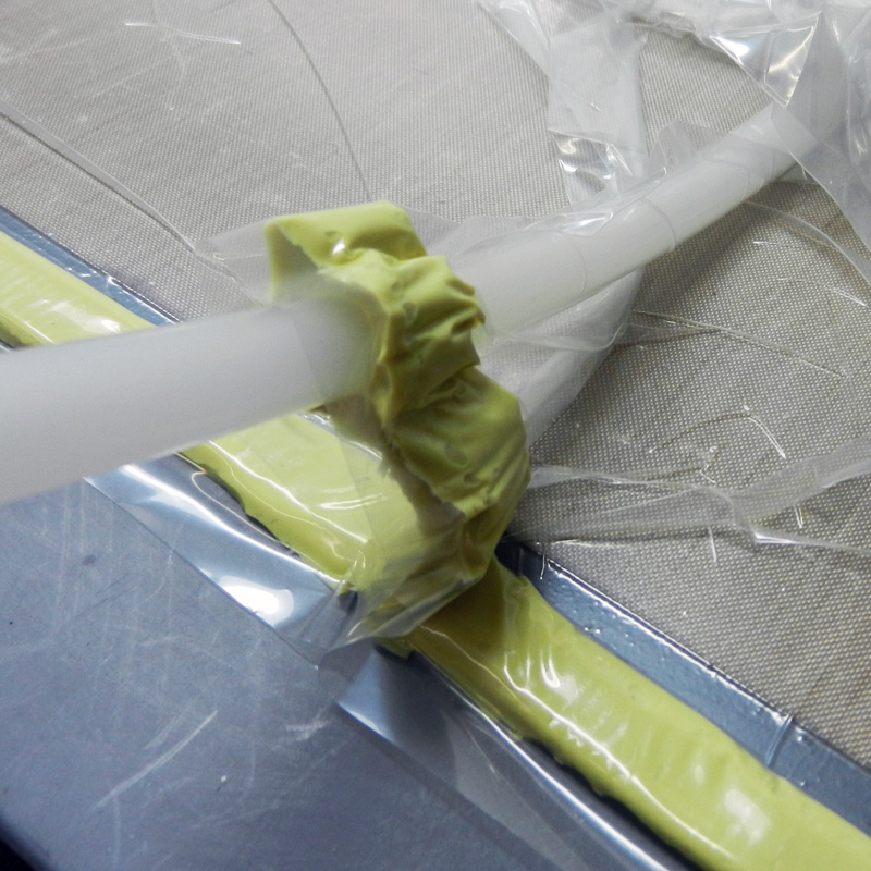
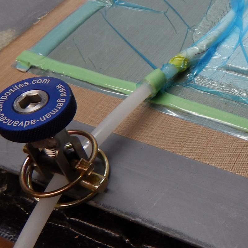
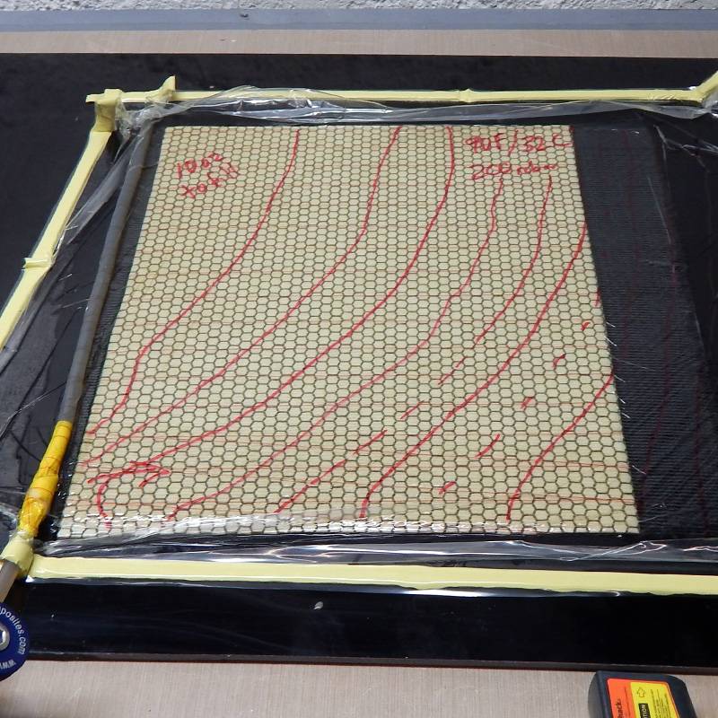
Also make sure you don’t block off the hose or the spiral wrap so that resin can’t enter the part evenly. The image at the right shows a wide stretch of tape holding the spiral wrap to the resin feed hose. This tape keeps the resin from entering along the whole edge of the part. The red flow-front markings show the uneven fill progression – which worked out here but would be problematic in more complicated situations!
For larger parts, you’ll want to put the feed lines through the bag. This is done by placing a T-fitting or “RIC” under than bag and into or over the feed line. Once the bag is drawn down, attach them to the bag. For a T-fitting, wrap the upward-facing part of the T with sealant tape, pop or cut away the bag, and slide the hose over, sealing it into the tape. For a RIC-style coupler, wrap the hose in sealant leaving about 1/4″ of hose extending down. Pop the bag over the RIC and fit the hose into the connector, sealing the tape to the bag. Be sure the bag doesn’t clog the hole!
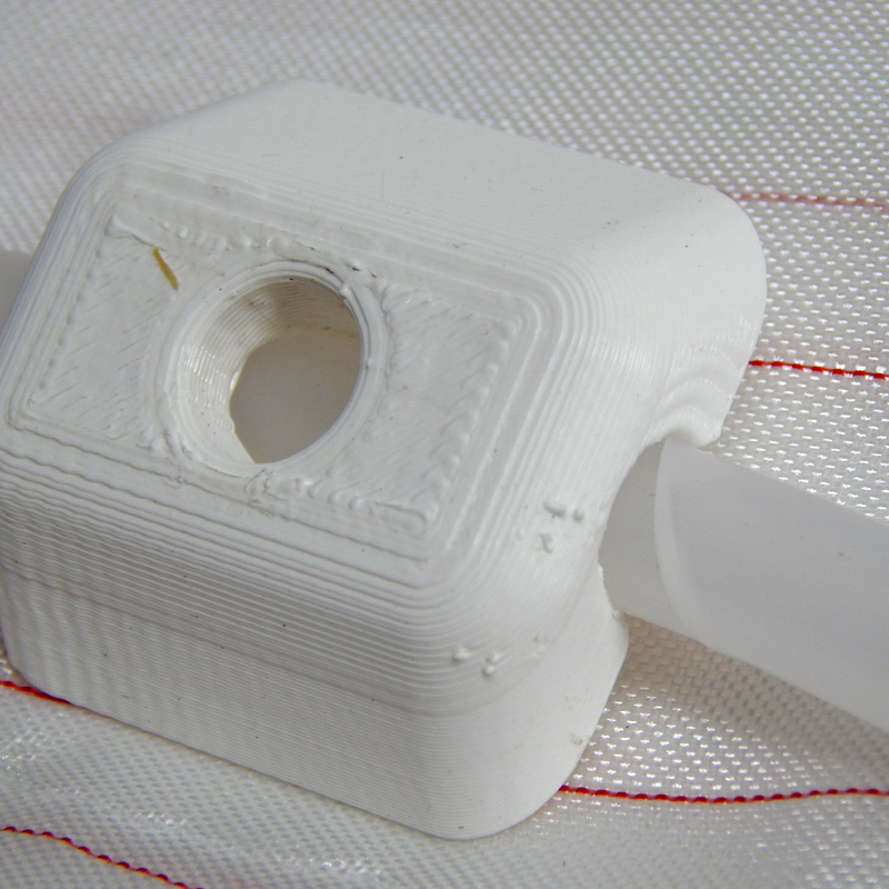
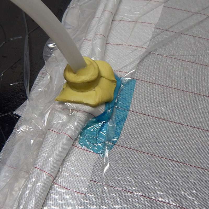
Bridging
If you have a bag that isn’t pressed into tight contact with the part everywhere, it is effectively leaving funny-shaped hoses through your part. These will cause resin “race-tracking” that can mess up your flow front and allow areas of the part to get “choked off” from the vacuum – leaving dry spots – aka: “islands”. This is bad.
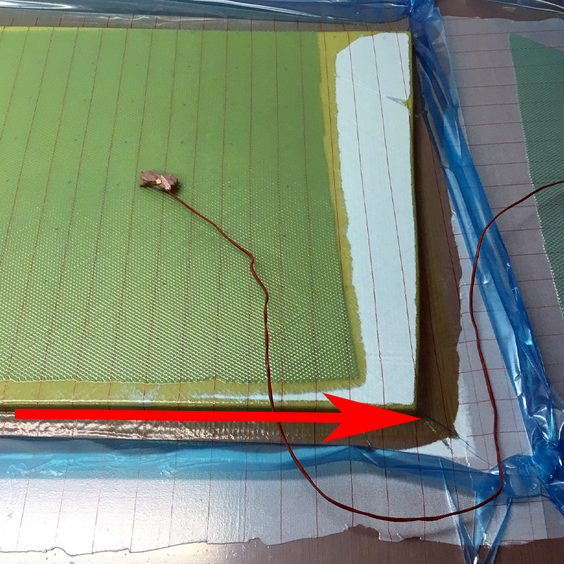
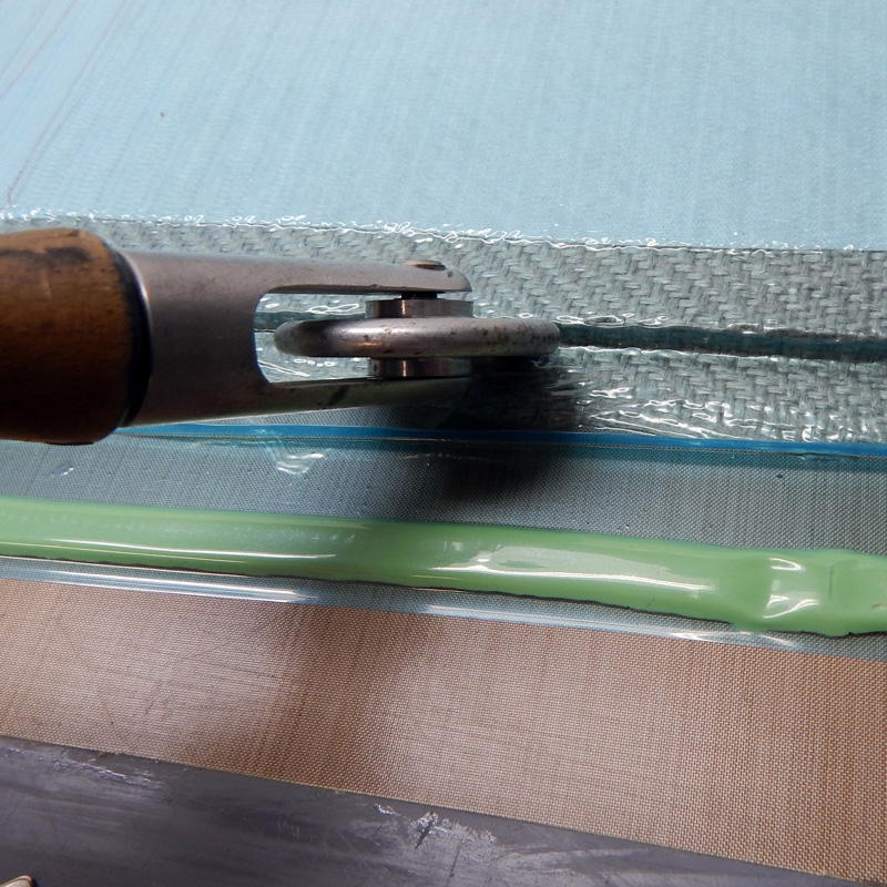
Make sure there is excess bag and that all the inside corners are pushed in tightly without any “springyness.” If you can push it in and it springs back you’ll have a big resiny (potentially voidy) corner. Rollers can be helpful, but the problem is best solved in the layup stage. Well sorted slip joints (even in the peel ply and flow media) will make this not a problem.
Before You Shoot
Your bag is on. The pleats are all nice, and the feed lines and vacuum lines are going where you want them all neat and tidy. The bag isn’t bridging anywhere – it’s tight into all the corners. The gauge is hooked up, on and you’re looking good. So how good are you looking?
Drop Test
If your bag has been pulled down for a while it is time to see how tight the bag is – if and how much it leaks. After a few minutes the vacuum level should be quite high (or low – depending on your gauge) and your bag all tight and looking leak free. My gauge reads in millibar (thousandths of an atmosphere) and full vacuum reads as zero. You can chase your tacky tape and fittings around until your vacuum level gets to near what your pump can pull. Check your pump vacuum first by connecting the gauge right to the pump and taking a reading. Only fairly nice pumps will pull near-full vacuum and you definitely don’t need one of those for successful vacuum infusion. It’s nice to do better than 28in/Hg or so though in most cases.
When it is really looking good – close a valve to your pump – you have a valve between your catch-pot and your pump right? You’re testing how well the bag stands on its own without the pump constantly sucking air out. Tis is called a “drop test” and what happens to the vacuum level will tell you a lot!
Chances are – unless you are a vacuum bagging wizard – the vacuum level will fall disconcertingly fast. Chase the sealant tape and fittings for leaks until it gets better. This is the value of a drop test – you see how leaky your bag really is. Once the resin front passes a spot in your tooling, there will be no more vacuum-pump pulling air out – but there will still be negative pressure – so the air from the outside will creep in and mess stuff up. Now’s your chance to find the leaks in the mold, the perimeter and the plumbing and make sure that your tooling is infusion-ready.
I have found that molds tend to be leakier near the perimeter and near complex features. If your tooling itself is infused, any mistakes in the tool infusion could result in pinholes in the tooling. If it is hand-laid or bagged wet-layup there may be porosity around the edges or around any spots where the mold itself had demolding drama from the plug. Damaged areas from prior rough demolding or handling can make for small and invisible leaks. Fittings are always suspect as are feed lines and the plumbing outside the bag. It doesn’t take much for a vacuum level to drop like crazy on a digital gauge – and in a way that you might not have noticed with even a nice dial gauge.
How much leakage is acceptable is up for debate and it depends on who you are and what you’re doing. NASA may have one standard – and I have another entirely! I generally go with small infusions if the drop test goes less than 15 millibar (0.5 inHg) in 5 minutes. This is pretty amazing really and even a much less tight bag will work for one-off stuff if you’re careful. Aerospace standards can be well below 0.01 inHg in 5 minutes – which is crazy hard to do even with a double-bag setup and perfect tooling. Generally the more important the part – and the larger the part – the more fussy to be. For things with low viscosity resin or long open time resin, the consequences of leaks are worse, so it pays to be more careful. One millibar per minute over 15 minutes is a common “higher standard” – this is equal to about 1 inHg in half an hour.
The goal is making sure it doesn’t leak through the mold face and that you can get a good perimeter seal. Leaks around the edge or “off the part” will have fewer consequences than leaks in the part area – where air leaking in will become part of your part! If your mold absolutely won’t hold a good vacuum, you can go over it with a leak detector or do a single layer sacrificial infusion and watch for bubbles. Often coating the back of a mold with resin will help – but you may have a bigger problem on your hands.
Resin Temperature / Mold Temperature
Resin viscosity and cure time / gel time are dependent directly on temperature. You really need to have a good handle on the temperature of your resin before you mix it and your mold loaded with dry stack. They should ideally be the same temperature unless you’re going for some fancy stuff!
Please avoid doing infusion cold. Below 65F / 18C and you’re asking for trouble. I’d suggest a much higher temperature – like 77F / 25C as a minimum. Especially with epoxy, warmer than that is even better. Most epoxy infusion resin is thicker than polyester or vinyl ester in the 300cps range at room temperature – especially tooling and fire retardant resin systems. You should have a range of hardeners to choose from so you can slow the cure down as much as you need if you’re worried about “premature gelation” of your part at high temperature. Uncomfortably warm is how I’d describe the best temperature for large epoxy parts. Everything works better – the viscosity, the moisture evaporation in the dry stack – it’s just a good way to get better results.
So do your infusions in a warm / climate controlled space, and make sure your unmixed resin is the same temperature as your tooling and dry stack. Warm resin will cool off as soon as it hits a cold mold. Cold resin will not have the low viscosity to flow through the feed-line system at an optimal speed. Have your point-and-shoot IR thermometer ready to check stuff all through the setup and shoot.
Resin Handling
Degassing?
In theory you should degass your resin. In practice, it’s less of a slam dunk. For processes where you need perfection, it is probably a good idea – especially with smaller volumes and epoxy. If you’re just making parts though and your process is dialed in and you feed at a reasonable rate through a dry laminate under high vacuum – you’ll probably be ok with a “degas in place” process.
The resin as it travels through the laminate stack will be subject to a very similar situation as resin in a degassing pot. It will be a liquid with some trapped air and vapor in it that is in a cavity with a vacuum. The air will be pulled out of the resin and away into the flow mesh and the vacuum side plumbing – through the pump and away! Also, this process will slow down as the part fills so you will have to deal with any trapped air in the resin that enters the part last becoming trapped and problematic. This is the weak-spot to not degassing – the end of the infusion is vulnerable to not getting degassed because a combination of feed breaks and resin breaks will trap air in the part instead of letting it flow off. Membrane infusion and membrane vacuum plumbing like Dahlvac or MTI hose will help with this because it allows air out but not resin.
Mixing in Batches
As soon as you mix a batch of resin and hardener – or resin and catalyst – the countdown to curing begins. If you mix a big batch but it sits in the pot for a long time as the part infuses, you may find that the larger volume in the pot starts to cure and makes a big hot exothermic mess before your part is infused. This is bad because it is a mess, and a waste, and a good way to ruin your part. For large parts it is a good idea to stage your mixing in batches as the infusion progresses and add “fresh” mixed resin to your feed pot(s) as needed. This is especially true of epoxy, where infusions can take longer, and the runaway exothermic reaction in a big pot of resin is more pronounced.
It is a good idea to “kit out” all the batches of resin (and hardener if you’re using epoxy – or catalyst if volumes are large) you’ll need and then mix them as you go. This takes a fair amount of coordination for a large job, and you have to be on top of things because just one bucket sucking air will ruin your day! Definitely a team sport for large infusions.
People typically use buckets or totes or even kiddie pools for resin buckets – often with a huge nest of feed-lines plumbed in. It is easier to feed fewer large resin buckets than more small ones – but you’ll use more feed lines. You’ll have a mixing team and people to monitor the feed lines and the levels in each bucket.
There’s tons of stuff that can go wrong if you don’t nail all the details. For large high-value jobs it is a good idea to hire somebody experienced with this to help with your your first few!
Metered Mix Machines
If you are in a production situation, it is a good idea to look into “metered-mix” equipment to dispense your pre-mixed or pre-catalyzed resin directly into your part or into a feed-bucket. Especially for catalyzed resins this can be a huge time-saver and results in greater consistency from part to part. Many machines have controllers that can measure out a pre-programmed “shot” of resin that is right-sized for your part.
Shooting the Infusion
When you are ready to go, do a final check and make sure you have:
- Good vacuum! Have you done a drop test? Leaks are problem #1!
- Everything at the same temperature.
- Resin breaks and segmented vacuum perimeter (or semipermeable features like MTI or Dahlvac hose).
- A catch pot – or several.
- Enough resin kitted out and ready to mix.
- Resin buckets with clamps for hoses so they don’t pull out.
- Hoses numbered on the bag and at the resin pots for large parts with lots of feeds.
- Adjustable resin feed clamp(s).
- A plan!
- An atmosphere of serenity and calm…
Start slowly and allow the resin to fill the feed grid before really opening up the valve(s). Make sure flow isn’t choked off anywhere by kinks in hoses or collapsed or blocked spiral wrap. Check the through-bag hose penetrations for visible leaks before letting the resin get too far into the part. The quicker you fix these the better – but you shouldn’t have any if your bag was good!
You should choose a desired feed speed and try to follow it by regulating the resin feed rate. This may be as fast as possible, but don’t use that as a default. Unless you are constrained by gel time, use the time you have to feed more slowly. Slower resin feed allows air and vapor to escape the flow front and keeps the flow front (ideally) more vertical and less wedge-like.
Monitoring and Modifications
Keep an eye on buckets/pots of resin as you feed. One big really bad mistake is allowing air into feed lines! If a feed line sucks air for even a second, all that air will either end up staying in your part, or will have to try to escape through the flow media to the resin front. Resist the urge to go do something else while the infusion is filling… ask me how I know!
Watch the resin front for streams of bubbles indicating a leak. As the resin fills your part, leaks in the bag will become visible as air enters the part and makes a stream of bubbles flowing toward the resin front. You should catch this as soon as you can and slap a piece of sealant tape over the hole – or some clear packing tape – or a bag patch.
If you have to stop one or more feed lines to add more resin to a bucket, this is fine. You may notice that air bubbles rise to the surface of the part when you do this – and this is ok too. They should blast off to the flow front once you re-open the resin inlet.
It is fair game to throttle multiple resin inlets to help your resin front progress more evenly.
Clamping Off
You may want to clamp off your resin feed before the part is completely full. This can be a good idea because there is usually excess resin around the inlet plumbing and features, and this takes time to work through the part. Better over-full with some resin in the catch-pot than not full enough. If the part is a production job, you will get a good idea of the speed and adjust your process documentation to specify the right resin volume and speed (hardener or catalyst + heat depending on resin type).
On large parts, you will almost always clamp off different feeds at different times. This is part of the plan. As you develop a better knowledge of a production part, you will know where it feeds quickly and where things lag behind. You can tweak your feed layout to try to equalize this as much as possible – but it is a good idea to have a system where feeds get clamped off sequentially. It makes it a more flexible process and gives you time to do things calmly and systematically.
If you get lots of hot resin in your catch pot it can melt the pot or create lots of gas and backfeed the part. This is no good and makes a huge mess. It is best to avoid even filling the vacuum-side plumbing with resin unless you have to. Usually this happens because of uneven flow rate or lack of an adequate resin break. If you find you are consistently filling resin into catch pots, try to adjust the vacuum perimeter plumbing and resin breaks to limit this. Also, check out semipermeable vacuum plumbing.
Vacuum Management
If you are concerned about vapor as discussed earlier, you may want to plan to reduce your vacuum level at the time you close off the resin inlet(s). This is a good idea with large epoxy jobs if you have concerns about moisture. For smaller parts with polyester or VE resin, it is probably not necessary – also not necessary to shoot these parts at full vacuum. It does help though, and it also reduces the risk of overbreeding parts by pulling too much resin out before it starts to gel.
Make sure you switch or dial back the vacuum before clamping off the resin inlet and causing the pressure on the part to increase. This alone can trigger bubbles if there is moisture present from core, reinforcements or contaminated hardener.
The Last Bit: Curing and Demolding
Curing
Allow resin to gel before adding extra heat. If you’re planning to postcure, this should happen once the resin is consistently gelled hard across the whole part. Heat isn’t a big deal but it causes things to change and change is bad when you just want your part to come out good! Vapor pressure changes with heat and volatile stuff (water, MEKP, solvents) can become bubbles. If you need to speed things up, either shoot the whole job hotter or wait until the resin gels – then leave the vacuum on when you increase the temperature. Always posture under vacuum if at all possible!
With epoxy-infused parts it is best to keep the vacuum on until you’re ready to demold. For polyester or VE infused parts, you should be ok to turn off the vacuum after the resin has gelled completely – these resins have a much more abrupt gellation profile and it all gets over much more quickly than with epoxy.
You may find that with thick parts or heavy duty single-skin areas, the resin exotherm creates a lot of heat. This can cause distortion in the part, discoloration (which is ok to a point but looks crappy) and worst-case – damage to the mold. There’s nothing like experimentation to answer these questions and it is better to start conservatively and work hotter and faster from there.
Demolding
Don’t demold your part until you are sure it is really actually cured… Ask me how I know! B-staged epoxy can crack easily under demolding loads and this is bad news. For styrenated resins, check cure by monitoring hardness – first on the Shore D scale (up to the mid 80’s) and then with Barcol 934. You should be able to watch hardness develop even after you have removed the bag from your part. Depending on your resin and state of postcure, you can see Barcol 934 of 30-50. You can check epoxy too, but it won’t usually get as hard and Shore D is a common measure. Your resin data sheet should give cured hardness information.
If you’re going to post-cure your part (usually only for epoxy) you’ll want to do it with the vacuum still on and the part still in the mold – up to the heat-tolerance of your tooling. If you are doing a two-staged post-cure with the first stage “supported” in the mold and the second “free-standing” – make sure the vacuum stays on for the supported post-cure. Even with fully gelled/cured resin, you don’t want to risk pre-release or warping of the part – or a CTE mismatch problem causing things to move while still warm and floppy. It seems like it wouldn’t be a problem but it is!
Demolding infused parts is pretty much the same as demolding any other parts – you just have lots of extra junk around the perimeter to remove and deal with. It is a good idea to remove the infusion consumables while the part is still in the mold because it is just easier to handle. If you have used an easy-to-remove flow media or a coated peel ply this should be pretty straight forward.
My best advice for demolding is to use shallow wedges (like really shallow) and to take your time. If you are in a rush like I am, you can (will!) break stuff. I am always amazed by how well a systematic approach to demolding works! Work around your part perimeter and make sure things are loose and then use wedges or some other means to “lift” the part out of the mold. Avoid big hammers. Have as few people as possible work on demolding. Be very careful about bending flanges or applying too much bending action to corners. You can crack stuff. With fiberglass you’ll see it, but with carbon it is all-too-easy to miss!
Conclusions
Hopefully it worked out. If it didn’t, you’re in good company. Lots of people make lots of messes trying to infuse parts. Be patient. If you have issues you can’t figure out, try to find somebody experienced to ask. Most of all – make sure you have no leaks!
If you’re the organized sort, it can be really helpful to keep notes and pictures of your work. With so many details and potential mistakes to make it really helps – not that I do it consistently or anything!
Extra Stuff
Infusion and Patents
Most of the common infusion processing techniques have been invented and patented. Probably the most important is the 1990 Seemann Composites patent on the use of surface flow media and surface distribution media, which is the basis for the method described here.